Model Train-related Notes Blog -- these are personal notes and musings on the subject of model train control, automation, electronics, or whatever I find interesting. I also have more posts in a blog dedicated to the maintenance of the Randall Museum Model Railroad.
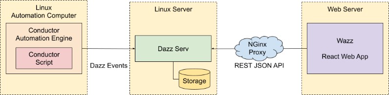
“Wazz” is my own web-based dashboard to get an instant overview of the automation at the Randall Museum Model Railroad. Last month, I started revamping the web site with a more modern implementation, and after about a month of work, I’ve just finished this major rework on the status dashboard with the following architecture:
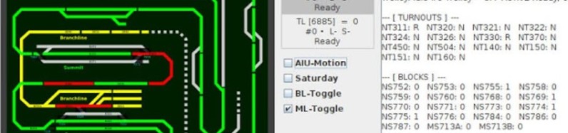
This now results in a web page giving a dashboard like this:
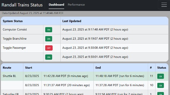
This page gives me an overview of which computers are on, wherever the automated lines are active (the “toggles”), and which train ran last, and whether it completed its run properly.
The major visible part is this new “performance” tab that lets me see how the trains behave on their respective route:
Click here to continue reading...
2025-07-07 - New Wazz Web Dashboard
Category Rtac
“Wazz” is my own web-based dashboard to get an instant overview of the automation at the Randall Museum Model Railroad. It used to be a crummy javascript single-page web page that I had hacked quickly over the years. I decided to entirely rebuild it using React, TypeScript, and Vite.
The source is available on the here: https://github.com/model-railroad/conductor/tree/main/web/wazz
And the web app is deployed here: https://www.alfray.com/trains/randall/wazz/
I used JetBrains’ WebStorm as the IDE; that was a nice step up from my usual VSCode setup. Not much to discuss on the implementation side -- it’s really your typical no-thrills React-TypeScript web app.
The Conductor automation software exports a JSON status, which this reads, and displays. There’s an automatic refresh every 10 minutes. Note that this isn’t hosted in any cloud -- it totally relies on the automation computer at Randall having wifi access to the internet. The uptime for that connection is around 95%. Since it’s mostly a remote view dashboard, I don’t need a perfect uptime, nor do I expect it to have a high traffic load.
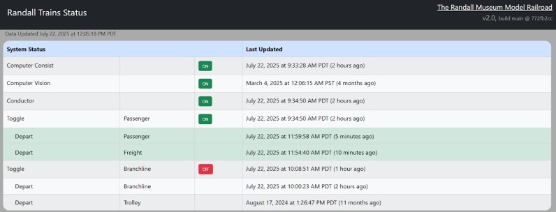
I’m essentially the sole user of that dashboard. Which also explains why the display may look cryptic -- it displays exactly what I want the way I want it, with no effort to be legible by people unfamiliar with the Conductor software.
This is the display I use for Distant Signal:
- https://www.adafruit.com/product/2278 $40, 64x32 with 4 mm pitch.
- https://www.aliexpress.us/item/3256808335479840.html, $18, 64x32 with 4 mm pitch.
Here’s the AliExpress one in use:

Using the AdaFruit version, here’s what the back of the panel looks like, annotated:
Source: AdaFruit.
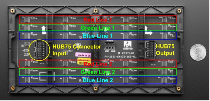
Notice the little vertical chips that are highlighted in Red, Green, Blue above. There are 4 x 3 x 2 of them.
The HUB75 connector is an industry ad-hoc connector. As far as I can tell, there is no solid specification anywhere to be found. Instead, it seems to have evolved over the years, and used more or less in a compatible way.
Click here to continue reading...
A bit more progress on the Distant Signal project: the initial configuration script consisted of purely graphics primitives, and the automation would select which of the predetermined states to display.
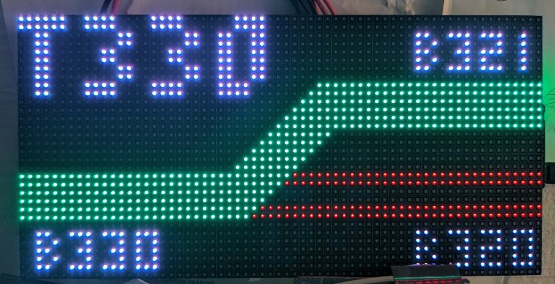
That’s good, but when I’m going to have several of these displays for several turnouts, I realize there’s a lot of repetition because each state represents the entire screen -- thus each state needs to repeat the title, or the block numbers, for example. Instead, the new direction is to have “layers” to avoid repetition:
- A title layer defines the display… title. That’s all.
- A “states” layer defines multiple track states for the given turnout (typically 2).
- A “blocks” layer defines the block numbers to draw next to the track, and that means we can now have active vs inactive blocks and thus render them accordingly.
With that approach, we can change the display to look like this:
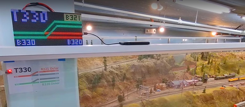
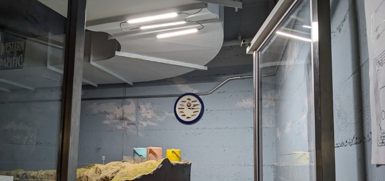
[Edit: And future me even added a view of this panel with a further style update, seen here in-situ:]
Click here to continue reading...
2025-03-26 - Distant Signal: Matrix Display for Turnout T330
Category Arduino
Here’s a new project, Distant Signal: https://github.com/model-railroad/distant-signal
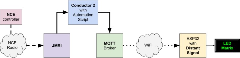
The goal of this project is to display the state of a remote model-railroad turnout on a LED Matrix Display. That’s obviously the “phase 2” of the single-LED ESP32 display I toyed with last week.
The hardware for this project is an AdaFruit MatrixPortal ESP32-S3 driving an AdaFruit 64x32 RGB LED Matrix - or more exactly some clone/equivalent of such.
Overall, the project works exactly the same as the single-LED version did:
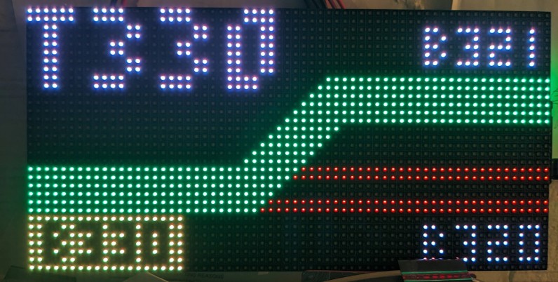
Here’s the first iteration of the display:
This version uses a basic text-based configuration script to define the content of the screen:
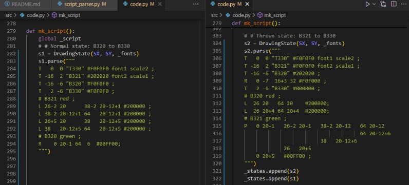
That’s the configuration script that the Conductor automation program would send to the display to initialize it. The configuration script defines several “states”, for example “T330 normal” vs “T330 reverse”. Each state is describes the entire content of a screen using a set of graphic primitives -- line, rect, text, and polygon.
Then MQTT would be used to select which state to display -- in this case turnout states, as the automation dictates which state should be displayed based on turnout sensor feedback. From the ESP32 point of view, the behavior is totally agnostic -- all it does is display a full screen of “something”.
2025-03-20 - Indicator for Turnout T330
Category Arduino
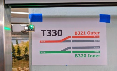
Here’s a new a experiment: we now have a new visual indicator of the position of the Sonora turnout T330, designed to be visible by the Saturday operators when standing at the Stockton Yard:
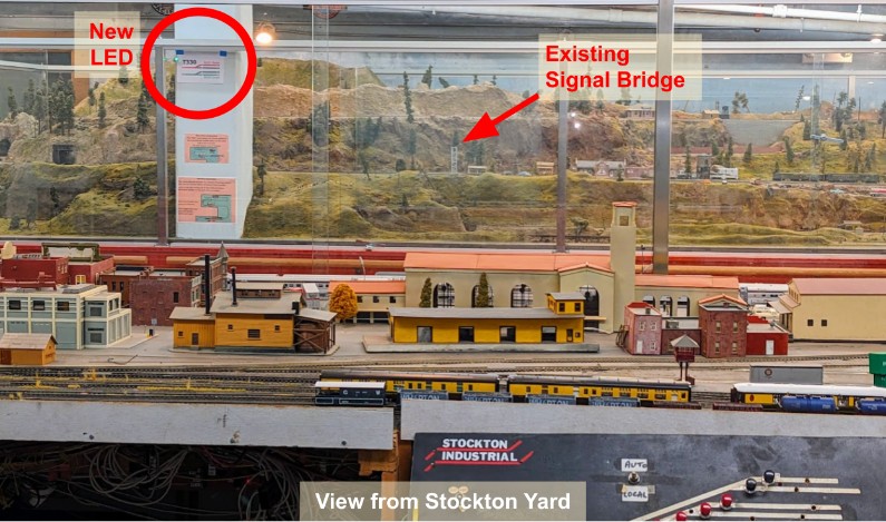
Sonora has the two mainline tracks that merge together at turnout T330, and there’s a signal bridge with signals that clearly indicate the position of the turnout. The problem is that the signal bridge is not visible from across the layout, where the operators are typically standing.
Thus this new experimental signal is located on the pillar -- it’s facing the operators, and it’s high behind the window, hopefully high enough to be visible even when the public is present in front of the layout.
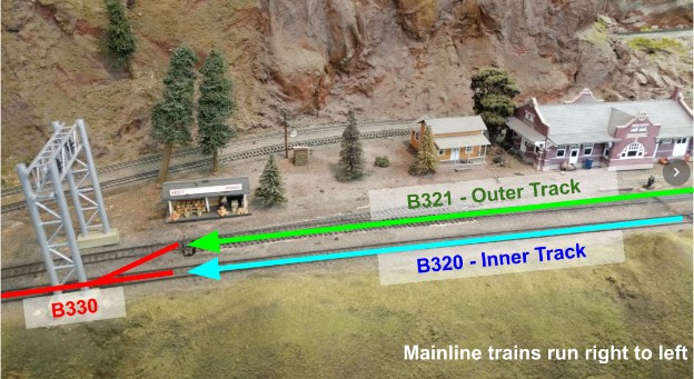
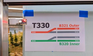
I kept the new signal as simple as possible: green indicates the turnout is aligned straight for the “inner” track (block B320) and red indicates it is thrown for the “outer track” (block B321). Behind the signal, I placed a short explanation to hopefully make it clear what the color represents:
Click here to continue reading...
Back in December I was fighting with the spurious block activation of block B360. This would break the automation, and I would have no real report about it. Of course I already have a custom web dashboard that shows me the status of the automation and after-the-fact analytics -- what kind of automation would that be without such dashboards? Still I figured having a “realtime” notification on failure would be better than periodically checking my custom dashboard.
I could add some email-sending capabilities to Conductor 2, but that’s something I’d rather not do as it’s a bit of its own rabbit hole. The Debian Linux computer running Conductor 2 has no email capabilities, and I intend to keep it that way -- I treat it as what it is, namely an unsecured box in a public museum with fairly loose access, thus it’s basically a DMZ.
Instead what I want is for the emails to be generated by some server that I control. All I need is to get the data to that server. I could piggyback the errors on the JSON used by the RTAC status server. That would almost be too logical. Or I could publish it on the MQTT broker and then proxy it over to the email server. Well, if I’m going that route, what about RSyslog?
So that’s what I did, and I get this kind of beautiful emails:
From: pi@alfray.com To: self@alfray.com Subject: New Automation Error Date: Wed, 08 Jan 2025 11:00:11 -0800
Jan 8 11:00:01 consist fireman: CONSIST ERROR: 10:57:38.342 R Sequence Branchline #3 Shuttle (0204) : ERROR Sequence Branchline #3 Shuttle (0204) current block <BLYouBet [NS760]> still occupied after 120.5 seconds. 10:59:38.892 R Sequence Branchline #4 Recovery (0204) : ERROR Sequence Branchline #4 Recovery (0204) current block <BLYouBet [NS760]> still occupied after 120.0 seconds. |
Here’s how I implemented this:
Click here to continue reading...
2024-12-25 - Conductor 2: Activated Block Handling
Category Rtac
These two commits address the recent issue of spurious block activation breaking the automation.
Recently a new sensor-related issue arose with block B360. Last time, it was because some track was occupied somewhere else on the layout. This time, the issue is different: the automated passenger train is going to Summit (the top of the mountain), where it stops and returns back down. It goes through these blocks:
B370 (Summit) → B360 → B340 → B330 → B321 → B311 (Station)
The new problem with block B360: after the train has left block B360 and entered block B340, block B360 should register as “empty”. After all, the train isn’t on the block anymore. But from time to time -- very rarely -- the block will keep staying on, sometimes as long as a minute and half! Now two adjacent blocks can be active at the same time -- that happens when a train crosses a block boundary. But once the train reaches block B330, it is an error for block B360 to still be active.
When that happens, the automation enters the error mode, stops the train, and tries to do a recovery. Interestingly as soon as the train stops, that “frees” block B360 too. Thus the recovery mechanism notices that only block B330 is active, deduces the train must be there, and brings it back home. From a viewer point of view, that all happens almost instantly so it’s hard to notice visually that something went wrong. But from a software perspective, it was all wrong for sure.
Click here to continue reading...
2024-12-16 - Conductor 2: New MQTT Support
Category Rtac
There’s been a few changes in Conductor 2 in the recent weeks.
The first major change has been to add MQTT support. The custom script language now exposes an “mqtt” object. Once configured, one can publish MQTT topics/messages. This is used to control the Ambiance LED string display. Here’s an example of usage in the latest script:
mqtt.configure("~/bin/JMRI/rtac_mqtt_conf.json")
mqtt.publish("ambiance/script/init", "Brightness 0.5 ; Fill #000000 1 ; SlowFill 0.1 #FF1000 40 #FF4000 10") mqtt.publish("ambiance/script/event", "Slide -0.05 100")
var _ambiance_counter = 0 fun Ambiance_Trigger() { mqtt.publish("ambiance/event/trigger", _ambiance_counter.toString()) _ambiance_counter++ }
fun Ambiance_Off() { mqtt.publish("ambiance/script/init", "Brightness 0.5 ; SlowFill 0.25 #000000 1") } |
Click here to continue reading...
2024-11-25 - Red Side Door USB Light
Category Electronics
This is what I used for the red door: https://amzn.to/43dp9e9 “USB Lights Bars 12 Inch, 3 bars chained”.
I’m powering this with a custom-made USB A-to-C adapter, which is turned off and on by a contact switch on the door. That works well, but it’s been bugging me because the light is stuck in the white-ish 9000K mode instead of the better looking 3500K 6500K mode. So I took one apart to see how it is built inside.
It contains a USB C with a 6-pin connector. That’s a “power-only” connector: GND / VBus / CC1 / CC2 / VBus / GND.
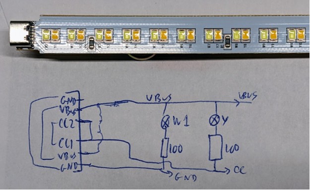
So essentially they “abuse” the CC1/CC2 lines as ground for the yellow-ish LEDs.
Click here to continue reading...