Model Train-related Notes Blog -- these are personal notes and musings on the subject of model train control, automation, electronics, or whatever I find interesting. I also have more posts in a blog dedicated to the maintenance of the Randall Museum Model Railroad.
2025-04-07 - Distant Signal: The HUB75 Protocol for LED Matrix Displays
Category Arduino
This is the display I use for Distant Signal:
- https://www.adafruit.com/product/2278 $40, 64x32 with 4 mm pitch.
- https://www.aliexpress.us/item/3256808335479840.html, $18, 64x32 with 4 mm pitch.
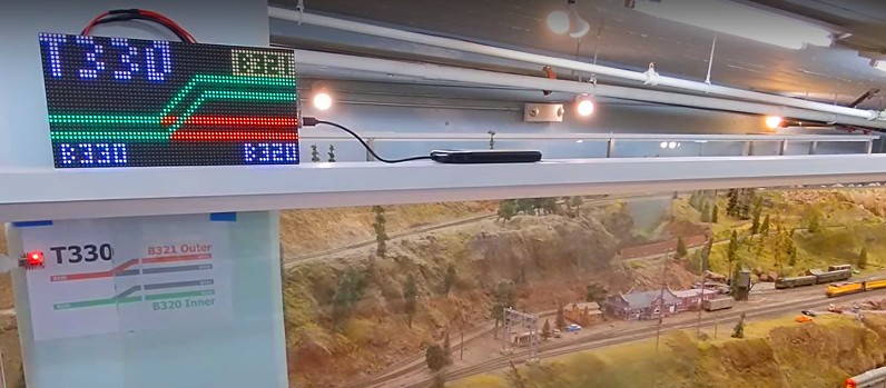
Here’s the AliExpress one in use:
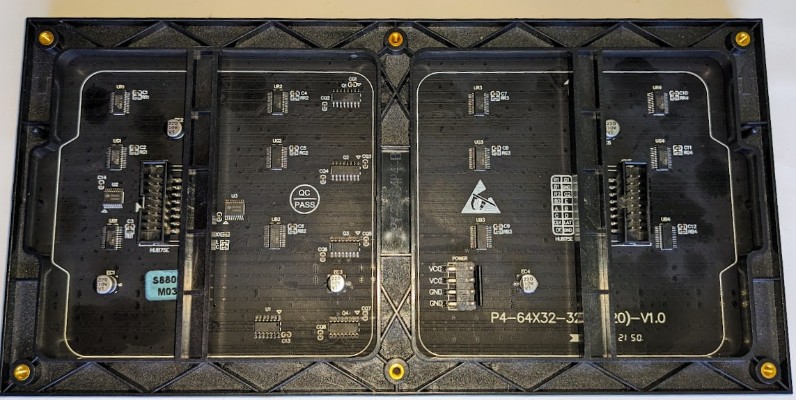
Using the AdaFruit version, here’s what the back of the panel looks like, annotated:
Source: AdaFruit.
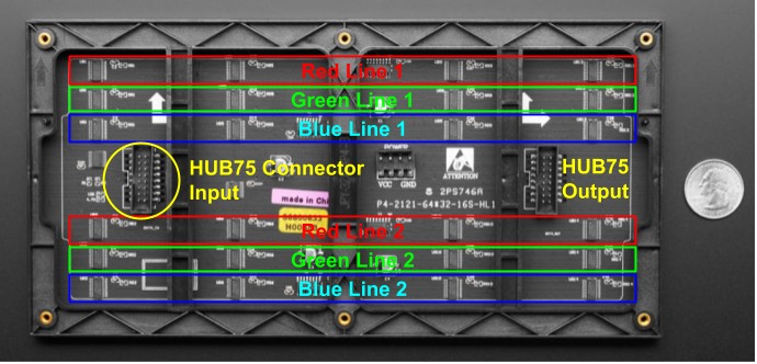
Notice the little vertical chips that are highlighted in Red, Green, Blue above. There are 4 x 3 x 2 of them.
The HUB75 connector is an industry ad-hoc connector. As far as I can tell, there is no solid specification anywhere to be found. Instead, it seems to have evolved over the years, and used more or less in a compatible way.
So here’s how this panel works:
- The panel has no memory frame buffer per se.
- The panel is composed of RGB LEDs that can be individually turned on or off. There is no variation on brightness -- each pixel’s RGB component is either on or off.
- The little chips highlighted in the RGB sections above are ICN2037BP -- these are “16-channel constant current sink output LED drivers” (datasheet PDF).
What this means is that each chip can hold 16 bits of data. 4 chips per line allows it to hold up to one line of 64 bits, and we need 3 of them per line to hold enough data to drive 64 RGB LEDs in one line.
Let’s keep in mind that this is a 64x32 LED panel. That’s a very important detail.
The connector is a bit puzzling at first:
HUB75 vs HUB75-E connector: Sources: lushaylabs and justanotherelectronicsblog.
I like how there are 2 ways to number the pins.
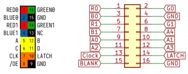
The HUB75 connector basically drives the electronics directly:
- There are pins to provide color data for 2 lines of colors, RGB0 and RGB1, at the same time.
- There’s an “address bus” consisting of 4 pins -- that’s 4 bits, which is enough to select one out of 16 lines.
So here’s how one displays one frame of image on a 64x32 panel:
- Turn the entire panel off using the /OE (output enable) pin.
- Select the one line out of 16 to update, from 0 to 15, using the 4 address pins.
- The panel has 32 lines yet we can only select one out of 16, how does that work?
- That’s why there are RGB0 and RGB1 pins: we fill 2 lines at the same time.
- The panel is essentially split in two halves vertically.
- Selecting the address 0 sends data to line 0 and line 16. Using address 1 sends data to line 1 and 17, etc., all the way up to line 15 and 31.
- Send 64 bits for 2 lines on the RGB0 and RGB1 pins.
- Note that each RGB component is either turned on or turned off for each pixel. There is no brightness selection here.
- The CLK (clock) pin is used to clock in the 64 bits composing the line.
- Once that is done, use the LATCH pin to copy the data into a second set of buffers that directly drive the LEDs. This is done internally in the ICN2037.
- Finally release the /OE (output enable) pin to allow the ICN2037 drivers to light up the select lines of LEDs.
- Rinse and repeat with the next line.
- Once the 16 “dual lines” have been processed, rinse and repeat for the next frame.
The take from that is that this panel only updates two lines of pixels at a time, but it’s a bit more than that: it only displays 2 lines of pixels at a time. Whilst 2 lines of pixels are turned on, everything else on the panel is turned off. Then the driver just needs to update all the lines one by one, fast enough to take effect of the natural persistence of vision to avoid flickering.
So now, back to that HUB75 connector: the number of address pins is inherently linked to the number of lines on the panel.
- A 16-line panel uses 3 address pins: A, B, C → 3 bits = 8 combinations, x 2 = 16 lines.
- A 32-line panel uses 4 address pins: A, B, C, D → 4 bits = 16 combinations, x 2 = 32 lines.
- A 64-line panel uses 5 address pins: A, B, C, D, E → 5 bits = 32 combinations, x 2 = 64 lines.
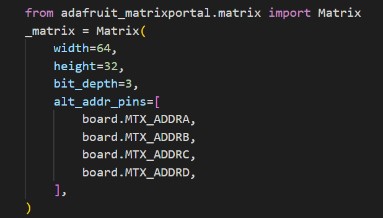
AdaFruit has a very convenient “Protomatter” library to drive these panels, and the Matrix class is initialized accordingly as such:
Now, when I did that on the AliExpress panel, it sort of worked but the display was only showing up on half the panel. The second half was always black. How come? Was it broken?
The AliExpress listing shows the back of the panel and it looks exactly like the one from AdaFruit.
But that’s now what I received. What I got is slightly different, and at first I totally missed the difference:
What’s on that board:
- 1x 74HC04D Hex Inverter (6 Channel)
- 2x DP245C “likely some 74HC245 clone” which is an 8-bit non-inverting transceiver (it has an 8-bit port A and B and transfers A to B or B to A depending on a direction bit).
- 3x ChipOne ICN2012 “8-Channel Power Switch for LED Display”
- 4x3 ChipOne ICN2037BP “16-channel constant current sink output LED driver”
The main differences are:
- There’s only half the ICN2037BP line buffers.
- The connector is a “HUB75-E” and has 5 address pins, like a 64x64 panel would have.
There is only one “line” of memory buffers: enough to buffer 64 bits for 3 colors, just one line, not two lines.
I posit that the RGB0 pins are used and the RGB1 pins are not used on the connector.
Instead, the line address selection is done using the 5-bit address bus: one line out of 32. This doesn’t do the “dual lines at the same time” trick from the other panel.
The other difference, which I noticed much later after I did all my research on how that “HUB75” works is actually written right on the panel, except it’s hard to see. Here are the part numbers on both panels:
- The AdaFruit is a P4-2121-64*32-16S-HL1.
- The AliExpress I received is a P4-64X32-32S(2020)-V1.0
(the vendor’s stock image has a different part number, too fuzzy to read)
Part of that is hidden behind the plastic support. What we can deduce from these part numbers:
- P4: The panels have a 4-mm pitch.
- 2121: That’s the size of the LEDs (2.1mm x 2.1mm)
- 64x32: That’s the number of LEDs.
- 16S vs 32S: Address selection is done using 4 pins (16 lines) or 5 pins (32 lines).
However, as I noted earlier, that’s not what is shown in the AliExpress listing. It’s apparently a common issue with ordering from there -- vendors will basically send whatever they have that looks more or less like the listing they are selling, with little regard for accuracy. The vendor who sent that probably thought “64x32 panel with 4 mm pitch, same thing, ship it! If the customer is not satisfied, they will rant, and then we can address it via resolution.”
I thought about returning it, but honestly, I’m fine. I realize the panel is not broken per se.
Does it conform to the HUB75 specification? Well, technically no -- it does say it’s a “HUB75-E” on it, so very honestly I could argue I did not receive a HUB75, as the listing claims to sell.
My rationale is that I go with the least effort. I could return it, but that’s effort. I could rebuild the Matrix C code for AdaFruit’s CircuitPython to support a panel with a “32S” specification. That’s a ton of effort.
And the least effort here is that I can trivially deal with this panel in AdaFruit using the CircuitPython driver without making one iota of modifications to the CircuitPython library:
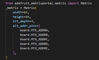
Yep that’s right: I just tell the library that I have a 64 lines panel. Then it expects such a panel to have 5 address pins to select one line out of 32. The only thing is that it means the underlying driver is storing frame buffers which are twice too large, but the MatrixPortal-S3 has way more memory than I need. It also needs to send that second RGB1 line of data, but it does so “at the same time” as the first one, so I don’t think there’s a noticeable performance penalty. OTOH it does mean the refresh rate of the panel is essentially half of the 16S version.
A note on power consumption: the AdaFruit docs as well as all the panel docs I found indicate that a 5V 4Amp power supply is needed to fully power the LED matrix panel. I’ve measured mine in my application and found that it typically uses anywhere between 1A and 2A max. The MatrixPortal-S3 powers the panel and it works just fine when powered by a regular USB C brick of 5V 2A spec. My guess is that the consumption is directly related to the number of LEDs simultaneously lit per line -- e.g. a panel that has all the RGB pixels fully lit on at the max refresh rate will inevitably consume more. Even that way, we need to remember that only one or two lines are really turned on at a given time (1 line for a 32S, 2 lines for a 16S), per panel, multiplied by the number of panels if they are chained.
Update 1: I recently found out that AdaFruit has a way to select the pin number of the Addr E on the HUB75 connector of the MatrixPortal S3. Apparently it can be either “pin 8 or 16”. My display matches the HUB75 connector schematic on the right above, with the Addr E on “pin 8”. Since it’s obviously being driven fine by the MatrixPortal S3, I did not change the jumper on the S3 itself.
Update 2: Since the initial prototype worked well, I ordered a couple more panels from AliExpress to expand the system to a couple other turnouts. This time though, I got panels which are labeled as “16S”. That’s what the original AliExpress listing was supposed to have sent, yet they didn’t -- a common issue when ordering from AliExpress, vendors will often send something that’s “more or less like the listing” and they expect end-users to complain if that’s a problem. The “16S” panel works directly with the AdaFruit Matrix class without the need to fake-double the number of lines.