The Randall Museum in San Francisco hosts a large HO-scale model model railroad. Created by the Golden Gate Model Railroad Club starting in 1961, the layout was donated to the Museum in 2015. Since then I have started automatizing trains running on the layout. I am also the model railroad maintainer. This blog describes various updates on the Randall project and I maintain a separate blog for all my electronics not directly related to Randall.
2025-05-27 - Research: Status of the Stockston Station Tracks
Category RandallI’ve quickly checked the Stockston Station tracks: which blocks have power, which turnouts work.
Turnouts:
- They all checked and worked “most fine”.
- T501 was a bit rusty but worked once moved a couple times. It has a mechanical oddity as it is offset and uses a wire to move the turnout.
- T513 is a common problem as Orion typically throws it to access Thomas and then fails to set it back to normal.
- All the turnouts seem to be Tortoise -- they were slow and did not make the characteristic Fulgurex sound. Needs to be verified visually.
Blocks:
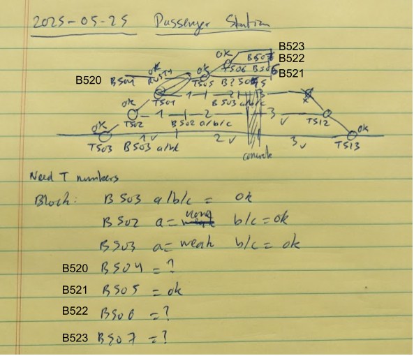
- On the Perry schematics, I noticed that tracks are labeled T3/T2/T1 as expected (with T1 being the inner one), and the top tracks are labelled GT1/2/3 -- I’m guessing for “garage tracks”. I could keep them as blocks B504..B507, or it would be worth giving them a different range of numbers >= B520 (we’re using T51x for the turnouts at the end of the station) such as B520 up to B523. See drawing above.
- In this case, we would renumber the turnouts accordingly? Maybe not.
- Track B503 tested fine on all 3 segments.
- Track B502 a and B501 a would not light up the LED light. b & c worked.
- Garage track B521 tested ok, but garage tracks B520, B522, and B523 did not light up the LED light.
- They also seemed to slightly turn on the light even when off.
One issue is that I have “dead/DC” engines and cars on these tracks.
I should redo the testing without the static display equipment, and I should measure voltage at the panel. Also I have a perfectly valid RRAmpMeter that would be awesome for that which I’m not using -- what we really need is a test involving a light bulb to force current consumption.
Looking at Plan+Sensors v7, this is what I had planned in 2017: Randall Map - Sensors 6.pdf
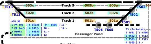
I already have AIU 50 in place: it has the B503 track + B504 + the motion sensor.
In the Presentation doc, I have the last “desired” mapping, the actual sensors used, and a projected drawing of the sensors board -- that was last updated on 2023: Presentation & Automation of the Randall Museum Model Railroad, ⁋19.5.1
Reusing this, here’s a revised view:
AIU01 address 50 for the Passenger Station Panel: (desired, 2025)
Bit |
JMRI |
Description |
Bit |
JMRI |
Description |
1 |
784 |
B503a (East) |
8 |
791 |
B502a |
2 |
785 |
B503b (center) |
9 |
792 |
B502b |
3 |
786 |
B503c (West) |
10 |
792 |
B502c |
4 |
787 |
B504 “Approach West” (East) |
11 |
793 |
B501a |
5 |
788 |
B510 “Approach East” (West) |
12 |
794 |
B501b |
6 |
789 |
B521 Garage Track 1 |
13 |
795 |
B501c |
7 |
790 |
B522 Garage Track 2 |
14 |
796 |
Motion Sensor |
Only B504, B503a, and B503b have BD20 on them.
We cannot add all the garage tracks: B520, B521, B522, B523. There’s only space for 2 of them, in which case I’d suggest adding B521 and B522 as these could be used by the automation.
Desired implementation steps:
- Need to bring DCC Turnout power for the Switch-8. We do NOT want to power it from the track or from the DCC breaker due to shorts.
- Prepare the physical space for both a Switch-8 and a BD20 panel.
- They don’t need to be mounted on the same support.
- Would it be possible to install the Switch-8 directly on the panel itself?
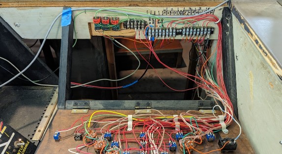
- ⇒ Seeing the picture above, I do not think so.
- The goal for the BD20 is to create a board with 2 terminal blocks, and then mount that board in the empty space liberated by the old JED plug.
- There’s already a terminal blocks for all the track blocks.
- I could reuse that, or I could replace by my own.
I wanted to create a “sensor panel” that I can mount and dismount. The first design had 2 terminal blocks, one at the top, the other at the bottom. I wonder if I should instead have both terminal blocks on the side side, or in a 90-degree configuration, to match the physical wire distance with the existing wiring.
Note that the terminal blocks I have are Uxcell “TB-15xxL” where the 2 last numbers seem to indicate the number of positions, and 15 is 15A max. I have sizes of 5, 6, and 12. Here I’d potentially want 14 positions. The pitch is officially 8 mm (I measured 8.8 mm).
Uxcell is just a rebranding shop anyway, but still we can search their site and find they go up to 15 positions for terminal blocks, but that seems uncommon and harder to find.
Space available & wiring can be seen in the picture above.
Interestingly the wires to the track come from the bottom of the terminal block. I also note that it has the 2 approaches, the DCC input, the turnouts power, the 3 station tracks, but not the garage tracks.
Depending on the slack available on the wires going to the bottom of the terminal block, I’d place the input/output at the bottom of the new sensor board, and then mount it in place of the existing terminal block, extending downwards. In fact the entire terminal block should be on the new sensor board? But then it would not be possible to easily dismount it.
I made a design for that board back in 2023, and I didn’t quite like it.
- Each BD20 is 20x36 mm. The first design had 11 BD20, for a width of 220 mm (~9 inches).
- The 2nd design staggered them in 2 rows of 6+5, for a width of 120 mm (~5 inches)
- But now I’d have 13 of them, for a width of 260 mm, or maybe 2 rows of 7+6, for 140 mm.
- The board included the Switch-8 (optional design #1) but not the AIU.
- I included 12-position terminal blocks, which now would not be enough.