NCE Button Board and non-momentary contacts |
2017-01
I use the NCE Switch-8 to drive Tortoise slow-motion motor turnouts which takes an add-on card, NCE Button Board, to support local control panels toggles. I originally selected this combo because the Button Board documentation clearly indicated that it supported non-momentary contacts. It turns out the NCE documentation is wrong and in this article I explore the alternatives to make this work.
This is going to be long, so here's a table of content.
3 - Technical Details of the NCE Button Board
4 - Non-momentary contacts are supported
5 - Non-momentary contacts are not supported, after all
6 - Reprogramming the NCE Button Board
7 - Arduino Replacement for the NCE Button Board
8 - Arduino, Second Act… For Science!
1 - Background Context
When working on the Randall Museum's layout, built by the Golden Gate Model Railroad Club, I have to deal with a control panel that looks like this:

All the turnouts are controlled using rotary toggles (non-momentary) that are directly connected to their corresponding Tortoise or PFM Fulgurex slow-motion turnout motors. They are wired as such:

For those not familiar with the term, a "momentary" contact is a push-button: a contact is closed when the button is pushed and the contact is open when the button springs up; if this were to control a light, the light would be on only when the button is held down and the light would turn off as soon as the button is released. By contrast a "non-momentary" contact is one that stays closed in whatever last position was used; a good example of that is a typical household light switch: when the switch is turned on, it stays in the closed position to close the circuit and turn on the light and it stays this way till the switch is thrown in the reverse position.
Here we have the same thing: each rotary switch has two positions and it closes a contact permanently ("non-momentary") in the direction in which it is thrown.
I originally choose NCE Switch-8 as an accessory decoder based on these four principles:
- That I was dealing with Tortoises, which the Switch-8 support.
- That I wanted to control around 45 turnouts total, so having a card supporting 8 at once was very beneficial.
- That I would connect to a local panel composed of non-momentary rotary toggles, which the NCE Button Board is supposed to support according to its documentation.
- That the board is not primarily powered by the DCC bus (shorts on the DCC power district should not prevent a turnout from being rectified).
Turns out the first principle was wrong and I realized the layout wasn't only using Tortoise but also Fulgurex turnout motors. I wrote a separate article on how to support these PFM Fulgurex Turnout Motor using an NCE Switch-8.
Here's the NCE Switch-8:

Power is provided from the DCC bus via the 2-pole terminal block on the top right or from a DC power supply via the barrel plug at the top in the center. Turnouts such as Tortoise slow-motion motors are connected to the A/B outputs at the bottom.
On the left side there are one or two 3-position terminal blocks. The documentation officially only has the upper one labelled "Button Board"; mine somehow includes a lower one labelled as "Relay Board".
2- The NCE Button Board
NCE sells the NCE Switch-It to drive up to two slow-motion turnout motors such as the Tortoise. These have direct contacts to connect push-button for local control (e.g. a fascia panel). The Switch-It documentation clearly indicates only momentary contacts should be used (either push-button or little up/down toggles with a spring) and thus this was not a choice for my case.
One will note that in the above description of the NCE Switch-8 nothing is said about local button control. Does it have no such support? Of course it does, using the add-on NCE Button Board.
Now, some people who are quick to find flaws and criticize everything have asked me why have a separate add-on board. In my point of view this modular design is a win-win -- it keeps the board simpler, those who don't need local control don't need to pay for a more expensive board with external terminals they would not use, and those who need them can add a simple board at a fairly reasonable price. If you have ever seen the complexity of a Digitrax SE8C or a CML DAC20, this board looks simplistic by comparison. And the documentation is accordingly trivial.
And the documentation indicates this supports both momentary and non-momentary contacts.
To make this clear, today the NCE store page for the Button Board clearly indicates "Must be used with momentary normally open (NO) Pushbuttons or toggle switches ". I do not remember if that was the case when I first did my research last year or whether it has since been rectified. The zendesk help page clearly indicates it support push-buttons and toggle switches. In both cases, my definition of a toggle switch is a non-momentary switch (e.g. like a wall light switch) unless specified otherwise. The documentation provided with the board and available on the web site here still explicitly indicates (see last sentence):

Consequently, I was initially extremely satisfied of that choice, having finally found something that seemed to explicitly support non-momentary contacts. All the others I had seen either explicitly did not support them (Switch-It, Switch-Kat) or were fairly ambiguous about it (DS64, DAC10/20).
All is nice, so I order a handful of these and start on it.
Wiring could not be any simpler, here is the Button Board on the left of the Switch-8:

Just 3 wires need to be connected: data (a serial port), and +/GND for power.
The power comes from either the DC barrel plug or the DCC of the Switch-8, depending on the switch selector on the Switch-8 board. The DC is delivered almost as-is (it goes through a diode so there's a minor voltage drop) and the DCC goes through a rectifier bridge first.
On the Button Board itself, the power is delivered to a small 7805 voltage regulator to get the 5 V for the PIC16F microprocessor. The Switch-8 already has its own larger 7805, so they could theoretically have sent that 5 V directly to the add-on board instead of having each their voltage regulator. However doing it this way means we can have a longer cable between the Button Board and the Switch-8 and not worry about voltage attenuation and parasitizing the 5 V line.
The Button Board is extremely simple. In the middle there's the PIC16F (the microprocessor) and its 6-pin ICSP header. On the side there's the 3-position terminal block for power and communication with the Switch-8 and the small 7805 voltage regulator. On top and bottom are the terminal blocks to connect the switches of the 8 turnouts (with Normal and Reverse pins for each) and finally on the other side is a 4-position terminal block all connected to the GND.
Each turnout pin has a pull-up and detection is made when the pin is grounded.
3 - Technical Details of the NCE Button Board
The board uses a PIC16F1936 microprocessor in its 28 pin package.
Datasheet: http://ww1.microchip.com/downloads/en/DeviceDoc/41364E.pdf
The board has a 6 through-holes "header" (on the left on the picture above) which is the PIC16F's ICSP (In-Circuit Serial Programming, see datasheet chapter 28, page 361).
The 6 pins, from left to right, when holding the PIC16 with 1 at the top-left:
- 1 = Pin 1 (Vpp / !MCLR)
- 2 = Header 1 with a 10k resistor to Pin 20 (Vdd)
- 3 = GND / Pin 8 (Vss)
- 4 = Pin 28 (ICSPDATA)
- 5 = Pin 27 (ICSPCLK)
- 6 = Not Connected
Note: Vss is the ground ref, Vdd is the positive supply, Vpp is the programming voltage.
Vdd max is +5.5 V and Vpp max is +9 V.
Only PicKit3 is supported by MPLab 8 or X for the PIC16F1936.
Checking the config bits, both CP and CPD in the config are set to ON.
Config1 is 0x0E24 (INTOSC, CP, CPD, BOREN); Config2 is 0x1CFF (BORV Lo).
There are 16 inputs (8 turnouts, Normal / Reverse each). Each input is wired from the terminal block to the PIC16F with a 10 kΩ pull-up resistor, a small capacitor to ground and another 10 kΩ resistor to the PIC16F input.
The PIC16F I/Os are used as such (PIC pin order with 1 on the top-left):

RE3 = Vpp / MCLR RA0 = Turnout 1 N RA1 = Turnout 1 R RA2 = Turnout 2 N RA3 = Turnout 2 R RA4 = Turnout 3 N RA5 = Turnout 3 R Vss RA7 = Turnout 4 R RA6 = Turnout 4 N RC0 = Turnout 8 R RC1 = Turnout 8 N RC2 = Not connected? RC3 = Onboard LED via 470 Ω resistor |
RB7 / ICSPDATA = ICSP Pin 4 RB6 / ICSPCLK = ICSP Pin 5 RB5 = Turnout 7 R RB4 = Turnout 7 N RB3 = Turnout 6 R RB2 = Turnout 6 N RB1 = Turnout 5 R RB0 = Turnout 5 N Vdd Vss RC7 / RX = Shunted to RC6 RC6 / TX = DATA via 100 Ω resistor RC5 = Not connected? RC4 = Not connected? |
The port/input order is inverted for turnouts 4 and 8 (this simplifies the PCB due to the way the pins on the PIC16 are laid out).
I didn't see anything obvious used for RC2, RC4 and RC5.
It's quite odd that RC6 (TX) and RC7 (RX) are connected together to the DATA pin of the terminal block.
According to NCE's the serial data output by the board works as follows:
The button board sends two bytes of data (9600,N,8,1) for each button 'event'. The first byte is the actual button data and the second byte is a complement of the first. The second byte when XORed with the first should yield 0xff allowing a modicum of error checking.
The button data is as follows (in binary): 1000 nnnn = button pressed, nnnn is the button number (0-F) 0100 nnnn = button released, nnnn is the button number (0-F) Bits 4 and 5 are reserved and may represent additional button numbers in the future so clear both bits when talking to a device that only expects up to 16 buttons. Some devices may choose to ignore button released events. |
Let's plug it into a small UART serial protocol sniffer. I'm using an Xmega XMiniLab from Gabotronics and I configured it to 9600 8 N 1 per specs:

The black wire connects ground to RX (pin 2) and the orange wire connects DATA to TX (pin 3) via a 4.7 kΩ resistor (needed by the Xmega when connecting a 5 V input).
The middle line of the display appears cut due to the refresh rate of the LCD and the cell phone.
Ignoring that cosmetic detail, we see something like this in the picture:
- Input #0 (turnout 1 N): 80 7F … 40 BF
- Input #1 (turnout 1 R): 81 7E … 41 BE
- etc. up to input #15 (turnout 8 R) starting with 8F (not shown here).
The first 2 bytes are sent when the input is connected to ground and the 2 next bytes are sent when the input is released.
This matches the doc, we have a push event followed by a release event. In the case of my non-momentary toggle switches, the release event will basically not happen till that turnout toggle is thrown back into its other position.
There's also quite some noise. For example on that screenshot, when asserting input #3, I see this:
- 83 7C 43 BC -- that's expected
- F3 7C 43 BC
- C3 7C 43 BC
- and finally 83 7C.
There are two interesting facts here:
- These two middle sequences starting with F3 and C3 are invalid as the first byte would not match the FF checksum. That's likely noise in my quick wiring to the UART sniffer.
- It ends with the proper 83 7C push event. The release event is missing since the input is still connected using the non-momentary contact so no release event was sent.
Interestingly, one of the many Button Boards I got does not behave the same: turnout #8 inputs (both N and R), when grounded, send a repeated loop of push/release events in rapid succession, whereas inputs for turnouts #1 up to #7 only send the push event when grounded and the release event when the contact is thrown in the reverse direction. Interestingly, turnout #8 is on I/O port C (RC0 / RC1) on the PIC16 whereas the others are on I/O port A and B. Somehow on this one port C must not be set up the same way. I can see how that infinite loop of serial commands might perturb a Switch-8 connected to it.
4 - Non-momentary contacts are supported
That's what the documentation indicates: this supports both momentary and non-momentary contacts.
Let's go for it!
I wired the whole thing this way:

The rotary toggles used on the original panel are actually 6PDT. I simply unsolder the turnout output and connect it to the NCE Switch-8. Then I use any unused input of that same rotary toggle to create a Normal/Reverse switch for the NCE Button Board.
I first did a quick test at home, connecting all this to my DCC system and it worked perfectly out of the box as advertised.
Then I started wiring one panel at the museum's layout and things went a bit differently: the Switch-8 part is fine, I had no trouble throwing switches by using the Accessory mode on the NCE ProCab throttle. The button board however did not work, I fiddle with it for a while then it worked. OK so maybe a wire was loose. Then I come back the next day and same the thing is not working anymore.
The Switch-8 was simply not throwing turnouts when a rotary toggle was turned, at least not consistently.
I started trying different things. Maybe the serial data wire was too long so I moved the button board closer to the Switch-8. Maybe I had to use the DCC or the DC power on the Switch-8. Maybe that power supply was not good and another one would be better. Maybe I needed a different voltage on the power supply so I tried different voltages in the 7-14 V range (the default was about 11 V, which seemed perfectly reasonable to feed to a 7805, and there was a good solid 5 V on the board behind it).
Eventually a pattern emerged: the thing would seem to work when I unplugged the barrel power plug of the Switch-8 and then plugged it back. It clearly seemed to work better when the board was power-cycled, with nothing supporting that in the documentation.
I eventually found a loosy workaround: power both the Switch-8 and the Button Board off the same DC power supply, with a switch so that the Button Board was powered first and the Switch-8 was powered after. For some reason that did seem to make it consistently work… for a while. After some time, the thing would stop working again. Clearly not suitable for my application.
5 - Non-momentary contacts are not supported, after all
Eventually I emailed NCE's support and the first and definitive reply came right away: toggle switches connected to the Button Board "MUST be momentary".
The story is that they found an issue in the programming after production. That could have used at least a clear rectification on the NCE web site to avoid having users pick up that specific solution for a reason known to not work (and by clear I mean actually writing "the documentation is wrong and non-momentary contacts are not supported", both in the zendesk help page and the store site -- as it is today, it's a confusing because they say different things and there's no indication of which one is right).
NCE support suggested an easy way to identify this as the cause and a partial workaround: add a push button on the common ground line that goes from the Button Board to the rotary switches, essentially turning a non-momentary contact on a momentary one. I did so and it effectively solves the issue right there. The procedure is of course not optimal since now the use case is to turn a knob and then have to remember to push the temporary button for the turnout to actually align.
Besides, NCE support indicates the Button Board does not work with non-momentary contacts and it will freeze the Switch-8. Yet somehow that is not what happens with mine. It does work for a while and the Switch-8 still responds to DCC commands. I have no idea how they programmed their PIC16 but I find that quite puzzling. I wish they could just share technical details about the core of the issue.
An interesting exercise would be to put my serial protocol analyzer between the Button Board and the Switch-8 and see what happens.
Update 1: The NCE support on this has been less than stellar. I got a first reply real quick indicating the doc was wrong, and after a few back-and-forth I got that hackish proposal to identify this has the issue. But then nothing. It's like my emails are falling into a black hole, which is quite disappointing and not a good prospect. Anyway, I need an actual solution and NCE support has apparently decided it's easier to ignore emails.
Since it looks like I'm on my own, let's see what options I have:
- Reprogram the NCE Button Board to fix the issue,
- Replace it by something else that works as I need it to with the existing NCE Switch-8,
- Replace the whole NCE Switch-8 + Button Board by something else, e.g. the Digitrax DS64 maybe.
Let’s explore how we can reprogram the NCE Button Board.
Update 2: Well they didn't forget about me. A week after I finished all these experiments, NCE support contacted me with a HEX file to reflash the NCE Button Board to solve the issue. I'll give it a try and report here.
6 - Reprogramming the NCE Button Board
The proper way to fix the NCE Button Board is to reprogram it to properly support non-momentary contacts.
The chapter above about the technical details of the board makes it clear that nothing prevents this. It's just a matter of programming it.
Disclaimer: Altering your board will likely void its warranty. Nothing here is endorsed by NCE.
The rest of this section is going to be quite technical. If you have no idea what all this means, please skip this section and check the next one, which offers a much easier way to replace the NCE Button Board.
(Update: NCE now has a proper fix; they can provide an HEX file to reprogram the board or they can be sent the boards and reprogram them for you -- but please make sure to contact the NCE support first and talk to them so that they can best help you.)
As indicated above, the NCE Button Board uses a PIC16F microprocessor, more exactly the PIC16F1936.
To reprogram it, we need a few things:
- The MPLAB X IDE.
- The MPLAB XC8 compiler.
- The MCC add-on for the MPLAB X.
- A PIC programmer such as the Microchip PICKit3.
- A Linux or Windows box.
Note that the PicKit2 is not compatible with this specific PIC microcontroller via MPLAB. That said, the PicKit2 is said to work with this device if using the old PicKit2 software, via 3rd-party linux command-line or in PTG mode; I did not try that.
I just wanted to keep it easy so I borrowed a PicKit3 at work (thanks Doug!) and used a Windows box. I also tried it under Ubuntu 16 and it worked out of the box (there are many comments online that say there are no Linux drivers for the PicKit3, I think they are just outdated… the MPLAB X installer added some udev rules and the PicKit3 was clearly recognized in dmesg, didn't even have to reboot).
Here it is in action:

When connecting the PicKit3 6-pin cable, the side with the arrow on the PicKit3 connects to the "1" side on the Button Board.
The source project I created for the MPLAB X is available here:
https://bitbucket.org/randall-railroad/automation/src/HEAD/pic16f/ButtonBoard2.X
Simply clone this using git then open the ButtonBoard2.X folder in MPLAB X and use the "Make and Program Device Main Project" button to compile the code and reflash the board.
I'm going to jump straight to the main user.c file, edited for brevity (I removed all the watchdog and led control as well as a bunch of comments; see the source here for the full version):
/** * Program for Button Board and non-momentary contacts, non-official version. * (etc. see full source for details) */ /* includes omitted */
// Number & Time in milliseconds to wait at startup to let the Switch-8 __delay_ms(DELAY_MS_BTN_RELEASE); sendByte(0x40 + index); } } for (uint8_t i = 0; i < MAX_INPUT; ++i) { __delay_ms(DELAY_MS_LOOP); |
Mode of operation is fairly straightforward:
- At startup, wait before sending any command to the NCE Switch-8.
- After the startup delay, scan the 16 inputs and send commands for all grounded inputs. Since this is designed to work with non-momentary contacts, each turnout should have a LOW input and a HIGH input. This means when the layout is powered up, all the Switch-8 will align to match the rotary toggles from the panels.
- After that, regularly scan the 16 inputs and send a command each time one transitions from a HIGH to LOW state (e.g. grounded).
- A command sent to the serial output for the Switch-8 is always comprised of both a push event followed by a release event, regardless of the state of the input. The release events are thus simulated, since they do not occur in any timely manner with non-momentary contacts. There's a pause after sending a command, which should be enough for the Switch-8 to throw the corresponding slow-motion motor.
This has been tested and works equally well with momentary contacts.
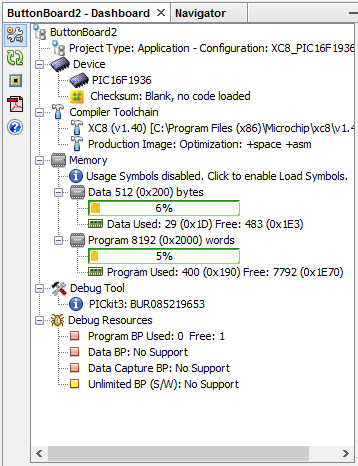
The resulting program is fairly small and uses only 400 bytes out of 8K available.
PIC Configuration:
- Configuration is done using the MCC.
- Lowest frequency usable is 500 kHz for a reasonable 9600 baud rate.
- WDT is activated, as well as STVREN, and both are probably overkill here. The watchdog time is left at the default 2 seconds value.
- PWRT MUST be disabled. Enabling it would make sense but somehow prevents the proper detection of the serial link by the Switch-8.
Detection of the serial data by the Switch-8 seems oddly finicky when it originates from the PIC on the Button Board. It seems to work better when the Switch-8 is powered after the Button Board, which is the reverse of the current hardware design.
I have none of these problems when I generate the serial data using an Arduino.
The PIC on the NCE Button Board comes with program protection, so don't bother even trying to read it as it will just read a bunch of zeroes. It can be programmed by erasing it completely though.
The first time, open the project properties in MPLAB X and configure the PicKit3 to power the target (PicKit3 > Power) and also disable Low Voltage Programming (PicKit3 > Program Options). Once you have flashed the new firmware that you have just built, you can re-enable Low Voltage Programming.

This concludes the "proper" and not-so-complicated way to fix the NCE Button Board.
Now let's look at another alternative.
There's a much easier thing to do to make this work!
7 - Arduino Replacement for the NCE Button Board
Ah, almost got you here. I said I was going for the "easiest thing" to do. Arguably, most people at that point would throw the NCE thing away and move on to something else (I think the Digitrax DS64 would be a logical choice).
But that's not what I'm after here. I'm curious how this thing can be worked out and exploring options.
The easy thing for me is: when in doubt, throw an Arduino at the problem.
That's an easy one. We need a device that can scan 16 grounded inputs and generate a 2-byte command on a serial port, knowing that the specs for the serial are clearly explained in the NCE doc.
Time to get an Arduino out of its drawer. I have plenty and they are a snap to program.
Let's see. I have a Digistump DigiX around, which is an Arduino Due clone with about 99 I/Os, wifi, sdcard and the kitchen sink. OK maybe that's a bit too much. I also have an Arduino Mega which has 50 I/Os. Maybe I can do smaller. An Arduino Uno or Micro doesn't have enough input. Oh there we go, the Arduino Nano is a good match:
- Input voltage is 7-12 V so we can just use the +/GND power supply that is given to the Button Board by the Switch-8.
- It has 22 I/O pins, but looking more carefully we have available D2-D13 (12 pins) and A0-A5 (6 pins).
Pins we don't want to use as I/Os according to the documentation:
- D0 / D1 are actually the RX / TX of the serial port, which we need.
- D13 is the on-board LED, we'll keep it as-is.
- A6-A7 are real ADC inputs, not usable. The rest of A0-A5 are actually the typical Atmel multi-purpose I/Os pins that can be used either as digital or analog.
So in the end we have 17 pins usable for I/Os and we need 16 of them.
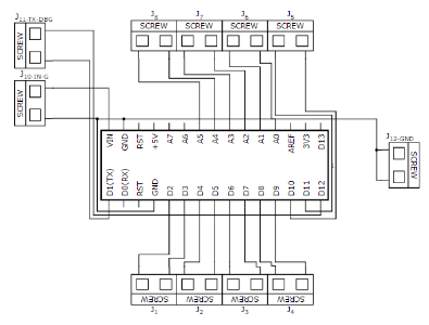
I ended up with this schematics and a potential PCB for it:

OK let's stop here. That's nice as it simulates the layout of the Button Board but it's too expensive. A PCB custom print is going to be around $20-$30 and one can get an Arduino Nano Terminal Adapter for much less:
This below costs about $4 for an Arduino Nano clone and $6 for a terminal adapter:
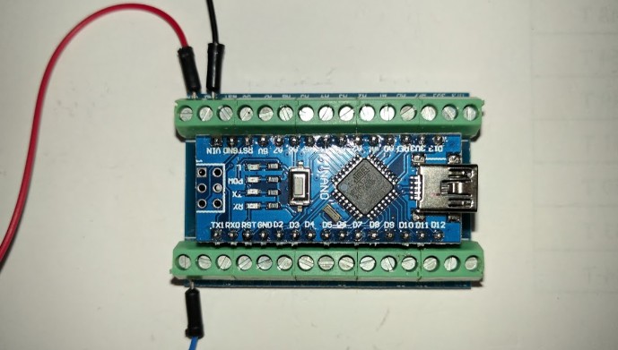
To use it, connect it as such:
Connections to the Switch-8's Button Board terminal:
- Pin 1 (TX1) to "DATA" on the Switch-8 terminal
- Pin VIN to "+" on the Switch-8 terminal
- Pin GND to "GND" on the Switch-8 terminal
Connections to the rotary toggles:
- D2/D3 : Turnout 1 N/R
- D4/D5 : Turnout 2 N/R
- D6/D7 : Turnout 3 N/R
- D8/D9 : Turnout 4 N/R
- D10/D11 : Turnout 5 N/R
- D12/D13 : Do not use.
- A0/A1 : Turnout 6 N/R
- A2/A3 : Turnout 7 N/R
- A4/A5 : Turnout 8 N/R
- A6/A7: Do not use.
- Use the other GND pin to connect to the other side of your DPDT or rotary toggles.
I threw together quickly this sketch for the Arduino, find it here on BitBucket, load it in the Arduino IDE and program it on the Arduino Nano:
/* #define DELAY_MS_START 2000
// Time in milliseconds to wait after sending a serial command to let the Switch-8 throw the turnout. #define DELAY_MS_SWITCH 1000
// Time in milliseconds before scanning next input. // This crude rate-limiter makes the sketch scan each input roughly once per second. #define DELAY_MS_LOOP 10
// Blink the LED for 100 ms. #define DELAY_MS_BLINK 100
// Time in milliseconds to wait before sending the button-released command to the Switch-8. #define DELAY_MS_BTN_RELEASE 500 |
All the I/O inputs use their internal pull-ups and the Normal/Reverse for a turnout is generated when the corresponding input is grounded. Pin 13 is used for the LED, it blinks at startup and when throwing a turnout.
Pin 12 was not used so I turned it into a debugging pin. When grounded at startup, the Arduino outputs text on the serial instead of the non-text bytes expected by the Switch-8. It should be left ungrounded in production.
Other than that, I used fairly conservative timings: when the Arduino is powered it waits a few seconds before doing anything, to give time to the Switch-8 to power up. When a turnout is thrown, it waits before considering the next input. This should leave enough time to slow-motion turnout motors to change their course. Finally the sketch is rate-limited by a short pause before scanning the next inputs. Play with the values and reduce them to what fits your turnouts.

8 - Arduino, Second Act… For Science!
OK this is going to be completely silly but bear me with, it's just for the science: we have a device that emits data on a serial port and that data is not quite as the other device that receives expects it to be. Or at least that sounds like a good description of the problem. What if we just filter that serial stream and reformat it to be what the NCE Switch-8 expects?
What I saw with the UART sniffer:
- The release event may never happen, or at least not on a "push button" timely manner.
- There are some invalid commands (arguably maybe noise in my sniffer set up, it wasn't the most tidy wiring).
- There's the infinite loop of commands from turnout #8 (arguably only on the first Button Board I tried).
What could help filter that serial data?
Oh I know: when in doubt, throw an Arduino at the problem.
Didn't I just say that earlier?
So here's the idea: take the TX output of the Button Board, feed it to an Arduino, clean up the commands and output a clean stream. Only look at push events and simulate release events. Dedup events to avoid repeating them in case the Button Board is stuck in a loop with turnout #8.

Well that's exactly what I've done here:

The Arduino Mega is absolutely overkill here but I had it already setup with the LCD and the XMiniLab on my "portable" experimentation board. Not shown here: the USB is then disconnected after programming and the Button Board connected to the +/GND supply from the Switch-8. That requires the Switch-8 to be powered by the barrel in DC, something in the 8-12 V range. The Mega is powered off that by wiring Vin to the + from the Button Board.
Then I wrote a quick sketch for the Arduino, which can be found here:
This is the gist of the sketch, I removed the parts dealing with the LCD for brevity:
/** * Serial Filter for an NCE Button Board. * (etc., see full source for details). */ #include <stdlib.h> #include <ctype.h>
#undef DEBUG #define LED_PIN 13
/** Milliseconds to pause before generating the release event. */ #define PAUSE_RELEASE_MS 250
// --------------------------------
void blink() { digitalWrite(LED_PIN, HIGH); delay(100 /*ms*/); digitalWrite(LED_PIN, LOW); }
void setup_blink() { pinMode(LED_PIN, OUTPUT); digitalWrite(LED_PIN, LOW); }
void setup_pause() { for (int i = 0; i < 4; i++) { blink(); delay(250); } }
void setup_nce() { Serial1.begin(9600 /*SERIAL_8N1*/); }
void setup() { setup_blink(); setup_pause(); setup_nce(); }
// -------------------------------
unsigned int serial_data = 0; unsigned int serial_last = 0;
/** Read incoming serial bytes in the buffer. */ void loop_read() { if (Serial1.available()) { int data = Serial1.read(); serial_data = ((serial_data & 0xFF) << 8) | (data & 0xFF); } else { // 9600 bauds = 104 us per bit = 1.04 ms per byte. delay(1); } }
/** Detect whether the 2 last bytes received are a proper push event. */ bool data_is_valid() { byte byte1 = (serial_data >> 8) & 0xFF; byte byte2 = (serial_data ) & 0xFF; if ((byte1 & 0x80) == 0x80) { if ((byte1 ^ byte2) == 0xFF) { return true; } } return false; }
/** Output the current push event followed by a simulated release event. */ bool output_command() { // Don't send the same command twice in a row if (serial_last == serial_data) { return false; }
byte byte1 = (serial_data >> 8) & 0xFF; byte byte2 = (serial_data ) & 0xFF; Serial1.write(byte1); Serial1.write(byte2); delay(PAUSE_RELEASE_MS);
// Release event uses 0x40 instead of 0x80 byte1 = 0x40 | (byte1 & 0x00F); Serial1.write(byte1); Serial1.write(byte2);
// Update last sent command serial_last = serial_data; return true; }
// -------------------------------
void loop() { loop_read(); if (data_is_valid()) { if (output_command()) { blink(); } } } |
That is silly yet it does work quite well and could actually be a proper way to "rectify" the issues with the NCE Button Board out of the box.
The Arduino Mega used in this experiment is of course inadequate. It uses too much power, especially with the LCD and the XMiniLab connected. This was powered via the DC power supplied by Switch-8 to the Button Board which I would not recommend. It's OK for a quick validation prototype but I would not run it that way for too long.
If I had to make something more permanent using this, I'd use a simple Arduino Nano, which is the most affordable one can find these days (about $4 per piece), add $6 for a terminal adapter to avoid soldering anything and will not draw too much power. But once I have that, I might as well use it to replace the NCE Button Board to begin with instead of trying to apply an ugly bandaid.
9 - Conclusion
To conclude, there are many options to fix the issue with the NCE Button Board. I'll recap them here:
- Contact NCE support, send them back the boards and they can reprogram them with a fixed firmware.
- Erase the NCE Button Board program and rewrite it yourself.
- Replace the NCE Button Board by an Arduino and program it yourself.
The "obvious" choice people should consider is of course the first one. Use your vendor's support.
I did want to show that it is sometimes easy to work around issues. One thing I do like with NCE hardware is that it is quite simple in design. It's all non-fancy no-nonsense dual-layer PCB with through-hole and surface mounted easy to see components. It's easy to understand and modify if needed.
Ironically I've heard comments of people saying NCE stuff looks "too simple". The provided documentation is a mere single page long. That's because it is, it's as simple as it needs to be and no simpler. Yes the boards don't looked crammed with tons of complex components and they don't come with a long and obnoxiously complicated documentation (I'm looking at you, Digitrax).
The Arduino replacement was an interesting find. It was trivial to replace and entirely skip the Button Board. Cost comparison, it ends up like this:
- NCE Button Board: $30 per unit.
- Arduino Nano + Terminal Adapter: $5 or $15 per unit.
- Arduino Nano cost is around $10 and you can get a clone for as low as $4 if you look properly. My experience with the clones is that they work fairly well and I expect 1 out of 4 to not work in a given batch.
- Terminal adapter are generally in $6+ range; if you look farther away, it's easy to reduce its price to around $1 per unit.
- Basic soldering is required to assemble it.
- Needs a computer with a USB cable and the Arduino IDE to program the Arduino.
- Time figuring it out: priceless.
So wait, would I recommend to skip the NCE Button Board and directly use an Arduino instead since it's cheaper?
Actually no, I don't.
Or I'd say it depends. It's the usual philosophical debate that I keep repeating:
- If this were for "my layout" at home, I'd go with the Arduino way. That's because playing with such electronics is part of the fun for me. I enjoy it. I also know what I'm doing and when I don't, I enjoy learning how to do it. I also consider that failure is an option -- things rarely work out the first time.
- Is it really cheaper? Because the raw components are cheaper does not mean the whole thing is cheaper. Time has a cost. The Arduino and the terminal adapter need to be soldered, and the whole thing needs to be programmed. And the program needs to be adjusted, and as I said, if things don't work, then it's more work to figure it out and fix it.
- The NCE Button Board hardware may be more expensive up front yet it's a plug'n'play solution. You buy it, you read the doc, you install it, and it works. Voila, done. No tinkering needed. It may look more expensive but it's not, the price is very fair for what is a nice piece of hardware well designed.
It's actually a bit deeper than that. The hidden cost is not in the initial purchase and setup, it's in the longer term maintenance. In my case, I'm wiring turnouts in a large layout in a museum. Years from now, some other folk will be there trying to fix whatever just failed, and although I will leave precise documentation behind me, maybe that doc will get lost. Will it be easier to maintain a custom looking arduino or that NCE board? With the NCE board, the future maintainer can just contact NCE, get a replacement, screw it in and be done with it. With the custom Arduino, it's likely the Nano won't be available anymore, or the terminal adapters won't be there anymore, or that github/bitbucket link will have been lost and the future maintainer will have no idea how to program the thing.
So in the end the proper solution is the NCE Button Board. And if you're like me dealing with non-momentary contacts that are not supported by your board, just contact NCE and they'll help you.
~~
~~