Model Train-related Notes Blog -- these are personal notes and musings on the subject of model train control, automation, electronics, or whatever I find interesting. I also have more posts in a blog dedicated to the maintenance of the Randall Museum Model Railroad.
2023-11-01 - SDB: VL53L0X ToF Sensor Accuracy
Category SDB
The Software Defined Blocks project uses an ESP32 with sensors to emulate block activations for a train model railroad.
The initial design called for the use of two ToF sensors, one on each side of the piece of track to automate. That would allow the automation to precisely stop the train on either side. The piece of track I want to monitor is about 3 meters long.
I selected the Adafruit VL53L0X “Time of Flight Distance Sensor” for this application.
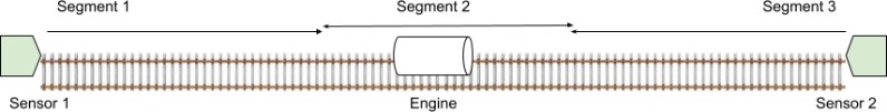
The specification lists the sensor as having a 30 mm to 1 meter range. The idea was thus to have 2 sensors, one on each side of the track to monitor, thus creating 3 “virtual blocks”: each sensor would monitor about 1 meter of the track, and if the engine is not detected there, we would assume it would be in the middle.
Unfortunately, as soon as I tried the sensor, I realized that it does not work for this specific application.
To make it clear, the Adafruit VL53L0X “Time of Flight Distance Sensor” works very well. It measures adequately the distance of whatever object is in front of it.
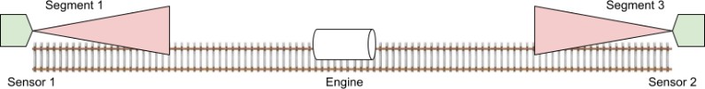
The issue is that I was expecting something like a directional LIDAR with a narrow beam. That’s not at all what the VL53L0X does! Instead the sensor produces a cone of IR light, and returns the distance of the closest point measured in its field of view. Here’s a more accurate representation:
The Adafruit page describes the sensor as a “narrow beam”, but when I think about it, it’s a fairly unclear statement.
https://forum.pololu.com/t/vl53l0x-beam-width-angle/11483 indicates there’s a FOV of 25 degrees, which is typically half of “good” sonar.
More docs at: https://www.st.com/en/imaging-and-photonics-solutions/vl53l0x.html#documentation
https://www.st.com/resource/en/application_note/an5894-description-of-the-fields-of-view-of-stmicroelectronics-timeofflight-sensors-stmicroelectronics.pdf ⇒ this is a general description of the type of FoV (exclusion zone, nominal, etc).
Actual datasheet: https://www.st.com/resource/en/datasheet/vl53l0x.pdf
- This clearly indicates the FoV is 25 degrees (section 5.1, page 23).
- We learn there’s a “temperature calibration” phase that needs to be done once and then redone if the temperature changes by more than 8 degrees (section 2.3.1, page 10).
- Timing budget of 33 ms is the nominal default value (section 5.3, page 25).
- There are profiles: default, high accuracy, long range, high speed.
- Long range is indicated as up to 2 meters, with a 200 ms timing budget.
- All others are up to 1.2 meters, with a 20-33 ms timing budget.
- This is a Laser Class 1 product, meaning it is “eye-safe under all operating conditions”.
- This embeds a microprocessor with its own firmware, and defines a precise API to interact over the I2C bus.
So, does this mean I can’t use this sensor?
Yes and no.
No, I cannot use it as I initially planned. I cannot take full advantage of the “1 meter” max distance, because basically the sensor always returns the closest object it can see, which happens to be the track itself.
However that only means the sensor has a shorter distance range of operation for my specific case. In particular, if I place the sensor around 2 cm above the track level, I am able to reliably detect any H0-sized engine which is closer than 20~40 cm. That’s a lot shorter than expected but it’s still quite useful since I am mostly interested in using the sensor to know when to stop the train engine at the end of the track.