Model Train-related Notes Blog -- these are personal notes and musings on the subject of model train control, automation, electronics, or whatever I find interesting. I also have more posts in a blog dedicated to the maintenance of the Randall Museum Model Railroad.
2023-02-25 - Split Core & Hall-Effect Sensors
Category Electronics
For now I’ve been doing block detection on the Randall layout using NCE BD20 current detectors. They work well. There are others DCC-compatible detectors but they all use through-hole core transformers, which means they cannot be used with existing wiring without desoldering or disconnecting something.
There are other contenders to the BD20, such as the cpOD and the CKT-BD1. I plan to switch to these once I exhaust my current supply of BD20. But the bottom line is that they all use these “through-hole CT”, and sometimes I wished I had the convenience of a split core transformer that I could quickly snap around a track feeder wire.
I had two goals in mind:
- Main goal: Have an alternative to the through-hole CT block detection sensors that do not require disconnecting nor cutting wires to install them.
- Secondary goal: Make a little portable “current detector” that I could quickly snap around a track feed wire to trace wire continuity.
Thus a while ago I got two sensors, with the purpose of figuring out to use them to monitor train track current with an ESP32:
- https://amzn.to/3q7qG4z Hall-sensing ACS712-5A current module.
- https://amzn.to/3AJM5FP Split core SCT013-005 5A 1V current transformer.
Spoiler alert: I discussed that topic on the MRH forum and the Arduini forum and I was clearly told that would not work, and to make a long story short, I never managed to make them work for this application.
Upfront I want to indicate why that was anyway not a surprise and I was likely to fail:
- My end goal would have been to connect the sensors pretty much directly to an Arduino or ESP32 with no other circuitry -- an important point -- and then deal with the sensor in software.
- By contrast the BD20, even though it’s the one with the simplest board, still clearly has 4 diodes (likely a bridge rectifier), 3 transistors, and a few other discrete SMD components. The cpOD and the CKT-BD1 have even more circuitry, including a small microcontroller likely to perform some noise filtering.
- The split core transformer I got as well as the ACS712 are typically used in home automation systems to monitor power line current anywhere from 1A to 100A, and at either 50 or 60 Hz. By contrast, current on a DCC track feeder may be maybe 2~4A max on a heavy load, and our DCC signal runs at 8 kHz. The dedicated block detectors above are extremely sensitive -- they will detect an engine not running and sitting idle on the track when properly configured!
Anyway, I’ve done the test and I failed. I’d venture one could still probably use these sensors with some additional circuitry, but I have not tried that… yet -- my goal was not to replicate the behavior of the dedicated sensors cited above.
BD20 Reference
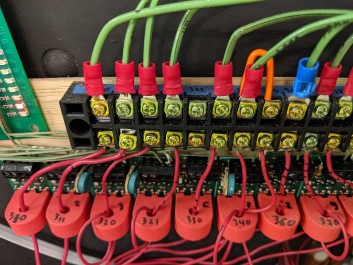
My reference is one of my BD20 sensors. These are designed to do just that -- block detection for DCC. It detects when an engine is on the track, even if it’s not running. This implies it’s sensitive enough to detect the current used by the engine’s decoder. It also detects lighted cars. When we want to detect rolling stock that does not have any active electronics inside, the typical trick is to glue a surface mount resistor on the axle between the wheels, and these can be in the range 5k-40kΩ.
To test the behavior of a BD20 sensor, I used a piece of test track connected to my DCC system. I don’t have a reliable amp-meter to use (the amp-meter in my multimeter died a while ago; I must have abused it somehow). So instead I’ve placed a 10kΩ resistor in series with one of the DCC wires and measured the voltage across that. The DCC is a square signal at 8 kHz and neither the DC nor the AC voltage measure of the multimeter are appropriate for this; instead I connected a small digital scope to the resistor and looked visually at the DCC signal on screen, approximately guessing the voltage peak-to-peak.
What I get is:
- Bridge rails with a 100kΩ resistor ⇒ measured +/- 0.12 mA ⇒ BD20 does not trigger.
- Bridge rails with a 22kΩ resistor ⇒ measured +/- 0.4 mA ⇒ BD20 does trigger.
- Bridge rails with a 10kΩ resistor ⇒ measured +/- 0.7 mA ⇒ BD20 does trigger.
- Placed an engine (idle) on the track ⇒ measured +/- 1 mA ⇒ BD20 did trigger.
All these measurements are approximate, but they give us a rough idea of the current that the BD20 can detect -- it seems to detect something as low as +/- 0.4 mA used symmetrically on the DCC signal. Let’s assume the circuitry on the BD20 rectifies the signal, that means they trigger a bit under 1 mA of current usage.
Let’s compare this with the two sensors I’m trying to use.
ACS712 Module
The https://amzn.to/3q7qG4z ACS712-5A is already mounted on a 3-pin “arduino compatible” board.
This one is rated at 5 amps, which is the minimum available.
Here’s the ACS712 data sheet from allegro:
- Chip: ACS712ELC-05B
- Supply power: 5V (min 4.5V, typ max 5.5V)
- Measuring range: 5A
- Analog output: 185 mV/A
- When there is no the detection current through, the output voltage is VCC / 2
Application note #4 shows output should be placed on a resistor divider for a typical 3.3V ADC. Shows a 1 nF cap on filter pin 6 -- without detailing what frequency cut-off that gives us here. There's a diode and a "user cap C1" too, without explanations either.

Do I need D1 & C1 on this application?
What is the schematics of the little board I actually got? Looking at it:
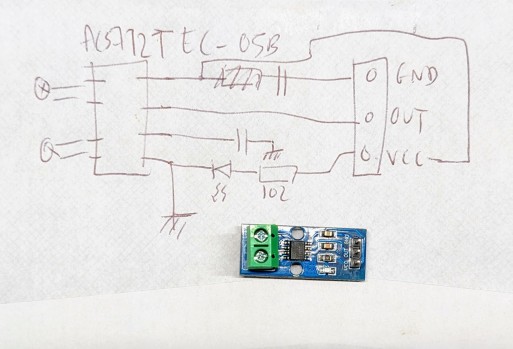
I couldn’t measure the values of the caps on the board, and I did not want to desolder them.
The design matches the application note:
- There’s a cap between VCC and GND. Let’s assume it’s 0.1 µF.
- FILTER pin connects to GND via a cap. Unfortunately that’s the one I’d like to know the value of and I can’t seem to measure it. It’s a slightly different shape than the one on VCC and we can infer it’s likely not the same value, whatever value that is.
- VIOUT pin connects directly to OUT with no other circuitry. It’s up to me to add resistors.
- LED is driven directly off VCC via a 1000Ω resistor. I couldn’t measure the Vf but looking at samples from Mouser a typical green SMD LED would be either around 2 V or 3.3 V, and let’s say 1V for a red one.
- 5V-1V=4V / 1000Ω = 4mA.
- 5V-2V=3V / 1000Ω = 3mA.
- 5V-3.3V=1.7V / 1000Ω = 1.7mA.
⇒ When trying the schematics above on a single wire of DCC bus with a single engine running, and looking at the output using a small digital scope, I get basically nothing but noise. Signal is at ~2.04 V and doesn’t move from there. By contrast, a single through-wire with a BD20 triggers instantly in the same conditions.
Let’s look at the spec above: 185 mV/A is the theoretical ratio. What does that give us, when we know our BD20 can detect as much as 1 mA?
If we want to detect 1 mA on the input, we’ll get 0.185 mV on the output. That is… not a lot.
If we were to feed this to an ADC on a theoretical 3.3V ramp at 10 bits, that’s 4096/3.3V*0.185mV = 0.23 ticks… Less than one tick of precision. We’re not going to measure that.
Let’s reverse this: 3.3V/4096 = 0.8mV is the least we could measure with one tick, which would be ~4mA on the input per ADC tick. We’re not measuring anything under 4 mA, and that’s not even counting the ADC noise. Upfront, that’s not going to work.
I’m not going to dwell too much on that sensor since I’d rather have something with the convenience of a split core that I quickly snap around an existing wire, without having to cut it. So let’s look at the other sensor
Split Core Transformer
The https://amzn.to/3AJM5FP split core is a 5A/1V model with a sampling resistor.
There are two versions of these split cores:
- Without a resistor: it’s a coil, and one measures current through it.
- WIth a resistor: a resistor in series with the internal coil, and one measures voltage across that resistor.
I have the latter one.
What’s inside:
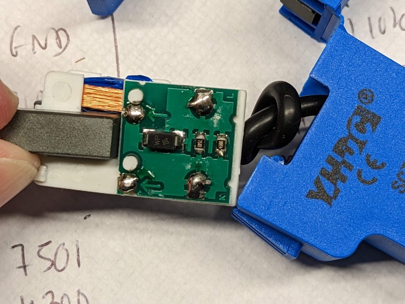
- An SMD marked “WP”. That marking could denote a diode or a “transient voltage suppressor”. The latter seems more likely, and matches the “TVS” indication on the datasheet linked above. Here’s such a Vishay component (to be clear I couldn’t recognize the logo on the TVS so I am in no way assuming it is a Vishay nor that one in particular). Did I mention I have no idea how a “TVS” behaves? What does it do to a 8 kHz signal?
- 2 resistors in parallel, marked 4300 and 7501: 430 Ω // 7.5 kΩ. Eq = 406 Ω.
Let’s compare this with the specs of 5A ⇒ 1V.
- U=RI ⇒ 1V = 406Ω * I ⇒ I = 1/406 = 2.46 mA.
- 5A/2.46mA gives a ratio of 1:2030 for the primary/secondary windings.
Datasheet found online, https://datasheetspdf.com/pdf/1328320/YHDC/SCT-013-050/1:
Some notes:
- Output is a 3.5 mm jack with 2 outer rings used (middle one “vacant”).
- All the ESP/Arduino schematics I find using the SCT013 in voltage mode power it via a 2-resistor voltage divider with a 10 µF cap (example). None explain why.
- Another one points out they use a 5V input, but I don’t understand what that 100Ω resistor does in there so I’m going to ignore this wiring schematics.
- Why use a voltage divider? Output will be zero and +/- so it’s easier to deal with if it’s centered on half the analog Vin reference voltage -- which is exactly how an ACS712 operates, which also makes all these Arduino sketches more or less interchangeable.
- It would make more sense to power the transformer from the 3.3V output of the ESP32, which is what the first example does.
We’ll use this schematic:
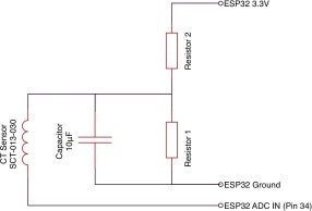
⇒ When trying the schematics above on a single wire of DCC bus with one engine running, I get basically nothing but noise. There seems to be a voltage when measured solely on the output of the sensor using the digital scope only. The scope registers it in the 24 mVmrs range. I can’t measure it with a voltmeter. It’s very inconclusive.
Even when trying to loop one DCC wire 3 times around the coil, I got absolutely nothing (I was naively expecting 3 times more on the output). By contrast, a single through-wire with a BD20 triggers instantly in the same conditions.
Let’s look at the spec above: 5A/1V is the theoretical ratio, which means 200mV/A (compare with the 185 mV/A ratio for the ACS712 above).
What does that give us, when we know our BD20 can detect as much as 1 mA?
If we want to detect 1 mA on the input, we’ll get 0.2 mV on the output. That is still not a lot.
If we were to feed this to an ADC on a theoretical 3.3V ramp at 10 bits, that’s 4096/3.3V*0.2mV = 0.25 ticks… We’re clear not going to detect that either.
Let’s reverse this: 3.3V/4096 = 0.8mV is the least we could measure with one tick, which would be ~4mA on the input per ADC tick. Not very different from the ACS712-5A indeed.
Here’s an interesting discussion about the issues with split core current transformers designs. The bottom line is that the through-hole versions have a much more efficient toroidal shape, whereas the split cores are less efficient due to their shape, with more magnetic leakage. And then we get to the frequency response. The materials used are apparently typically optimized for power line measurements (50~60 Hz) or for the higher frequencies of switch mode power supplies (20 kHz). It’s nice to know our application, at 8 kHz, falls perfectly out of both categories.
Speaking of frequency response, let’s play with that schematic above a bit more.
R1+R2 is a voltage divider, listed as “either 10kΩ or 100kΩ”, connected to either the 5V or the 3.3V Vout (the schema above clearly calls for the latter).
Impedance of C + R1 in parallel: 1/Z = 1/R1 + jwC where w = 2.pi.f
https://keisan.casio.com/exec/system/1258032649 calculator:
- C = 10 µF
- f = 8 kHz, R1 = 10 kΩ ⇒ |Z| = 1.9894367492791 Ω
- f = 8 kHz, R1 = 100 kΩ ⇒ |Z| = 1.989436788255 Ω
- f = 50 Hz, R1 = 10 kΩ ⇒ |Z| = 318 Ω
- f = 50 Hz, R1 = 100 kΩ ⇒ |Z| = 318 Ω
We can see why “10 or 100 kΩ” doesn’t make a big difference here.
I’m not going to compute the impedance of (R2 + (R1 || C1)). I’ll leave that pointless academic exercise to the bored reader.
Another way to see it is that R2 + C forms a low-pass filter if we ignore R1. Let’s compute the cut off frequency at -3 dB using fc = 1 / 2.pi.R.C:
- R2 = 10 kΩ ⇒ fc = 1.59 Hz
- R2 = 100 kΩ ⇒ fc = 0.1592 Hz
So this will be filtering our 8 kHz massively, as expected.
Let’s do the reverse computation:
- fc = 8 kHz, R2 = 10 kΩ ⇒ C = 1.98 nF ⇒ C//R1 |Z| = ~7.1 kΩ at 8 kHz
- fc = 8 kHz, R2 = 100 kΩ ⇒ C = 198 pF ⇒ C//R1 |Z| = ~71 kΩ at 8 kHz
- fc = 10 kHz, R2 = 10 kΩ ⇒ C = 1.59 nF ⇒ C//R1 |Z| = ~7.8 kΩ at 8 kHz
- fc = 10 kHz, R2 = 100 kΩ ⇒ C = 159 pF ⇒ C//R1 |Z| = ~78 kΩ at 8 kHz
Side note: -3 dB is ~70% of the signal, which is why the ~7k/70kΩ impedance above is to be expected as being ~70% of R2.
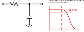
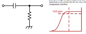
As a reminder, low-pass vs high-pass (copied from digikey):
The bottom line is that all these example schematics are designed to measure 50~60 Hz AC current so I’d have to expect to adjust the cap value for my 8 kHz need. From a discussion on MRH/Arduini, I should expect the magnetic core/coil to be improperly matched for my needs in the first place, and as seen above obviously the capacitor would need to be adjusted.
The original goal was “without added circuitry”.
Now, could we make this work, with some added circuitry? I tend to think maybe a bridge rectifier on the output would be useful, and/or a transistor to boost the current out of the coil would make sense (if using the current version). Since this one measures voltage around a resistor, my first thought would be to use an op-amp in a typical open loop to get an “infinite” gain. That would allow me to use it as an “all or nothing” detector like the BD20 does, assuming I can differentiate a signal from just noise. I was actually thinking we should use the property of the DCC to create an 8 kHz band filter and filter just that.
I have not even addressed the second elephant in the room, namely the fact I was planning to connect that to one of the ESP32 ADC inputs. The ESP32 is notorious for having a passable / sub-par ADC, with noise, offset, and non-linearity, made even worse by contamination when its wifi/BLE radio is used at the same time. This is typically “solved” by using an external ADC over I2C, which is a bit ironic and sad. Andreas has a full video explaining the issues and comparing it with better solutions.
Bottom line, we confirmed neither sensors are appropriate for the task “as-is”, with no added circuitry. That’s exactly what comments in MRH & Arduini indicated, and it was worth verifying. I may revisit the topic of the split core transformer later with some added circuitry.