Model Train-related Notes Blog -- these are personal notes and musings on the subject of model train control, automation, electronics, or whatever I find interesting. I also have more posts in a blog dedicated to the maintenance of the Randall Museum Model Railroad.
2017-10-31 - NCE AIU and Short Trigger Events
Category NCE
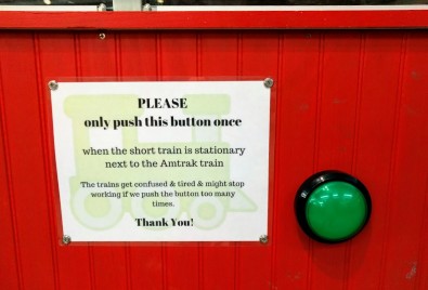
On the Randall layout, visitors press a button to trigger the trains’ automated sequence to start. Very quickly we noticed that sometimes the system would fail to notice the button was pressed.
We use a large button but that’s irrelevant. The issue has to do with how long it is pressed. Most people give a quick short push, and that’s the problem.
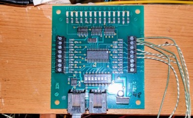
The button directly closes the contacts on an NCE AIU01 (Auxiliary Input Unit), which is regularly polled by the NCE command station. The computer runs my Conductor software which polls JMRI for the status at at least 30 Hz. The AIU01 is polled by the NCE Command Station at an appalling low refresh rate due to the NCE cab bus implementation: if an input doesn't trigger long enough (e.g. 1 second), it will be easily missed. In this case, it’s enough to give a short but quick push to the button and most of the time miss the polling window. The event is simply missed.
Question is what would be the simplest circuitry possible to make an input trigger longer?
From the NCE AIU01 pdf:
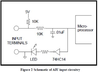
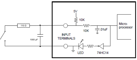
There's a grounded common and a 5V pull up on each input.
- When the input is open, the Microchip input is pulled up and the inverter sets the other side of the LED to low.
- When the input is grounded, the Microchip input is pulled low, protected by the 10k resistor and the inverter sets the other side of the LED to high, thus lighting it.
The obvious way is to use an NE555 to generate e.g. a 1-second pulse. It can be powered by the 5V from the NCE AIU to make sure they share the same ground and power (both 5V need to match to be a closed circuit). This requires at least one RC circuit on the 555, and we need one per input to deal with. Potentially an NCE AIU has 14 inputs, even using a 558 (a quad 555) would still require 4 chips and some wiring or a PCB.
At the other extreme, the “simplest” circuit would be to not have any extra circuitry at all. One option I do not have is reprogram the NCE AIU. I don't think NCE would give me the source, which is too bad because I could just trivially do the 1-second delay in software -- or more exactly, sample and latch any trigger input till the next read from the NCE bus.
A more "modern" solution would be to stick an Arduino in between, e.g. an Arduino Nano is fairly cheap. How many would I need for 14 inputs? 18 pins usable per Nano e.g. 9 inputs and 9 outputs. The Nano can be powered from the 5V from the NCE AIU and would basically simulate the inputs for the AIU. Although at that point, I’d basically add an RS485 shield to the Arduino and consider getting rid of the NCE AIU to begin with.
The cheapest and simpler solution (as in "less wiring") would be to put a capacitor on the input, it should lower it slowy and then raise it slowly. That would introduce a delay into the trigger and the release so it might be good enough. The time constant to reach 63% is τ = R x C. Say the capacitor is fully discharged. We have R=10 kΩ, τ=1s ⇒ C=100 µF and τ=0.5s ⇒ C=50 µF. That's not unreasonable. There should be some resistance in series with the button to not fully short the capacitor say something like 100 Ω or 1 kΩ.
And I tried just this, using R=110 Ω and C=1000 µF because that’s what I had around. A full long button press activates the signal for a good 5-7 seconds after release. Even a very short button press still activates the signal for a couple seconds.
The one consequence is that when powering the DCC, the signal is activated as the capacitor charges for also the same amount of time. This is not a problem since I have a full laptop with JMRI that needs to boot and it takes way longer than the initial charge time.