The Randall Museum in San Francisco hosts a large HO-scale model model railroad. Created by the Golden Gate Model Railroad Club starting in 1961, the layout was donated to the Museum in 2015. Since then I have started automatizing trains running on the layout. I am also the model railroad maintainer. This blog describes various updates on the Randall project and I maintain a separate blog for all my electronics not directly related to Randall.
2024-02-11 - Potential Power Loss in Stockton Yard
Category RandallI have had reports from Saturday Operators of trains slowing up and down when leaving the yard, not maintaining constant speed. I’ve personally seen that too when trying the newly fixed UP Walthers engine a few days before. Then a few minutes later, everything was acting normally in both cases.
One possibility would be dirty track. The pads of the track cleaning train are filthy and haven’t been changed in a while. However that would not explain why the issue goes away after a short time.
The other possibility is an electrical issue. What we need is a way to measure the track voltage and see if it changes. I don’t have a RRampMeter at hand for the task, yet we can easily replicate that using scrap components I have around already.
Thus, I made a “voltmeter car” to display the track voltage:
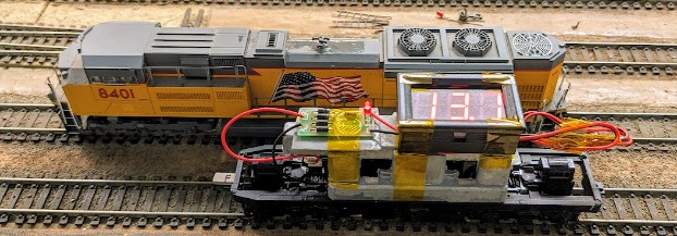
What you’re looking at in the picture above is a donor chassis from an old DC engine, and a few components I had at home: a “full” bridge rectifier (I removed the smoothing capacitor) connected to the track power pickups, and on top a basic voltmeter display. The idea is to measure the peak of the DCC signals as if it were a DC one, which should be more accurate than a multimeter in AC mode (we’re not doing AC Vrms here).
I removed the bridge rectifier’s smoothing capacitor since we want to see instant variations. On the other hand, since there is no smoothing capacitor the display cuts in and out each time the car moves and loses electrical contact. Thus we’re going to use this by keeping the voltage car static, on the booster/district to measure. The other engines are to be moving around it.
Next we need to understand if the issue is by circuit districts, or boosters, or what.
List of booster and circuit power districts:
- Booster 1 covers P1 V1 (Valley1), P1 STKYD.
- Booster 2 covers P2 V2 (Valley2), P2 NAPA, P2 TOWN LODI, P2 FAIRFIELD.
- Booster 3 covers P3 MTN-1, P3 BRN RCH-2.
- Booster 4 covers P4 MTN-2, P4 BRPORT, P4 SIA RND, P4 STK STN.
Issue was thus reported (and observed) on Booster 1. Each circuit power district has an NCE EB1. I don’t expect these to alter the voltage. If there’s a fluctuation, I’d tend to think it’s going to be from the NCE 5-amp booster or any other equipment left on the yard -- after all we have quite a number of engines and cars in there too that can affect the electrical properties of the entire district.
After building the “voltmeter car”, I did a quick test by Stockton Yard -- mainline at this place and yard are on the same booster. I saw on P1 STK YD:
- Voltage at 13.1 ~ 13.2 V
- When running 8401, voltage dropped to 12.9 V and then seemed stable. This is an older Walthers engine and these draw a substantial amount of current.
- When running 8312, voltage kept at 13.1 V and then seemed stable. This is one of the newer Walthers engines and they draw a fairly small amount of current compared to our older stock (I know that because that made them harder to detect on the NCE BD20 for the mainline automation).
This may be expected. At that point we just need to collect data first:
- Check the voltage in different booster / power districts of the layout.
- Leave the voltmeter car in Stockton, so that operators can visually see it if they observe the same issue.