The Randall Museum in San Francisco hosts a large HO-scale model model railroad. Created by the Golden Gate Model Railroad Club starting in 1961, the layout was donated to the Museum in 2015. Since then I have started automatizing trains running on the layout. I am also the model railroad maintainer. This blog describes various updates on the Randall project and I maintain a separate blog for all my electronics not directly related to Randall.
2020-01-19 - Arduino/Servos Turnouts
Category RandallHere’s the next thing to for Randall: explore creating turnouts using servos + arduinos, to replace the old twin-coils that fail in the yards.
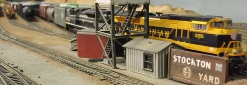
Let’s take the example of the Stockton yard. The ladder has 8 tracks, and about 9 twin-coil turnouts. At least 2 of them are failing -- they do still throw, but they short. The panel uses route push-buttons that align the track turnouts and the two lead turnouts. There’s a diode matrix on a panel below the yard, and I have a schema for it somewhere in a piece of paper, although that one is simple enough to just recreate the matrix by hand.
Let’s say hypothetically I’d want to rebuild the turnout machines in that yard. What are the options?
First, we need to understand what we have here. The twin-coil turnout machine is just one part of two functions: it moves the point of the turnout of course, but it also drives a contact to change the frog polarity. The twin-coil is driven not directly by the panel, but by a diode matrix -- the panel is a route selector, and not directly controlling individual turnouts. Finally, one thing we do not have here is integration with the DCC (no accessory decoder to control the routes or turnout via DCC cabs for example) nor integration with the automation computer.
The typical way to replace them would be to use Circuitron Tortoise turnout motors. That’s what most people go for these days. They are very reliable, we have many on the layout already, and they perform the two same functions (moving the point and changing the frog polarity). However I can’t just replace a single twin-coil by a tortoise, since the former uses a 2-wire short impulse, and the latter uses a permanent polarity for control. Using tortoises here only makes sense when the whole yard is converted.
On top of that we would need something to control the tortoises, for example an NCE Switch-8 with 8 outputs. That will allow for both computer-based and DCC/cab-based selection but not for routes from the panel. For routes, add an NCE Mini Panel. Its programming is a bit cumbersome, yet it does get the job done and it does not create a dependency on the automation computer. Cost-wise, we’re looking at roughly 8 x $18 + $65 + $45 = $254.
Of course we have options. A popular alternative is the DCC Specialties Wabbit which can control two Tortoises, so we need 4 of them here. That would change the cost to 8 x $18 + 4 x $25 + $45 = $289.
One positive aspect of this is that if a component dies, it’s easy to source and replace. The Switch-It / Wabbits and Mini Panel do require some programming, which is all done using a DCC cab, which means anyone could do that if given a proper instructions sheet with the sequence of CVs to enter. It does not require dedicated computer knowledge.
The other “obvious” way to do turnouts these days is using arduinos and servos. I have looked at that in the past, and I think this year it is time I get something going on.
The less obvious way is to have a mix. Use servos yet control them using off-the-shelf accessories like the Tam Valley Depot Quad-Servo Decoder, which here can control up to 4 servos. Tam Valley Depot has a number of really good designs; for example I already use their frog juicer setup as an auto-reverser for the Napa balloon track. Their quad servo decoder card also takes an add-on which has relays to switch frog polarities. In this case:
- Using the Quad-PIC: 2 Quad-PIC, 2 relay add-ons, and 8 servos, for an approximate cost of 2 x $40 + $2 + 4 x $7 + 8 x $10 = $190
- Using the Octopus III: 1 octopus III, and 8 servos with snap switch: $43 + 8 x $11 = $131 and an extra $20 for the DCC-control add-on.
Another good source is Model Railroad Control Systems; a lot of their cpNode and CMRI-oriented products can be easily repurposed when “thinking outside the box”.
Before I dig into turnouts, I’d want a more isolated project. One thing I’d like to get done this year is rebuild the Fairfield crossing that was stolen by Martin Chow. That’s a good place to have a single dedicated arduino controlling the lights and a servo animating a cross gate. My goal is that, instead of actually using an arduino, I’ll use an ESP32-CAM and use the camera module to detect the presence of trains, instead of relying on the typical light sensors or IR-reflective sensors. One thing is that we do not need to interact with the DCC, or the cab-bus, or the automation -- this is a completely isolated circuit, which simplifies things quite a bit.
Looking forward, I wonder if I could use a simple arduino + servo to replace a twin coil. There are examples of using a servo for turnout, yet these typically miss the frog polarity handling. OK, let me rephrase, as it’s obvious that a servo can be used for a turnout: I wonder what it does take to come up with something simple that is used in place of an existing twin coil. Same as above, we just need a fully isolated circuit, no need to deal with DCC. Upfront, I’d suggest something like this:
- A servo, obviously.
- A custom L-bracket mount, 3d printed or made of wood.
- One arduino per servo, at least. An Arduino Nano can be as cheap as $3 per piece.
- A dual-channel opto-coupler or opto-isolators HCPL2630 that can cope with the 12 V input, or a two zener 3-5V diodes.
- An SPDT relay that can be used to select the frog polarity (single pole, dual throw).
The arduino inputs are the two wires for the twin-coils. These receive either 6 V AC or 12 V DC from a common aux bus. I believe most of the twin-coils at Randall are AC only. By feeding that to an opto-coupler or a zener, we can both get rid of the AC part easily and convert that to a 3 V signal that won’t damage the arduino inputs.
The arduino sketch is basically just monitoring the input, and then switching the servo 90 degrees left or right. We might want to be able to easily define the resting position -- the default position when the layout is powered can be fixed and reset every time, or be left as-is.
Of consideration:
- The arduino servo library can control up to 12 servos per arduino.
- For what I remember, an Arduino Nano has about 18 usable I/Os. For each turnout we need at least 2 inputs and 2 outputs (relay + servo), thus one Nano could control up to 4 turnouts.
- The servos can all be powered by a single arduino or by multiple arduinos (one each). In the former case, there are limitations on how many can run at the same time. It’s easy to architect the sketch loop to deal with each turnout in sequence, thus only running 1 or 2 servos at a time.
- The Arduino Nano power input is either via a 5 V USB, or 7-12 V DC. The latter is easily provided by the mainline turnout power bus (we feed the tortoise & fulgurex around 11 V).
Cost estimate, very rough and optimistic: $3 per servo, $5 per relay, $3 per Arduino Nano (clones), $1 per opto-isolator: 8 x $3 + 8 x $5 + 2 x $3 + 4 x $1 = $74. And a lot of dev time.
It’s worth noting that in this scheme, I am replacing individual twin-coils switch machines by one servo, and an arduino potentially shared with up to 4 servos. That’s why there is no input from the panel -- this would still use the same hardware setup where panel buttons defines routes and setup multiple turnouts via the existing diode matrix. I’m not replacing that at all.
It is worth noting also that in this scheme, we do not tie anything at all to the DCC nor the automation computer. There is no DCC turnout feedback or remote control. That however could be added by having some kind of communication with the computer, e.g. via an RS485 bus, wifi, or wired ethernet. There are arduino libraries to decode DCC or decode the NCE cab bus (RS485).
As usual, the typical conundrum is whether to go for off-the-shelf components or custom made. The former is more expensive yet easier to maintain/replace, whereas the latter is less expensive in component parts and trades that off for time spent in R&D. Programming is done for the Mini Panel using a CV setup (cumbersome in my opinion, yet requires little computer skills), vs in the latter a Arduino sketch needs to be programmed (easy, in my opinion, yet I can see how a number of folks would not care for that); most important in the latter case, a full custom-made solution needs to be understood before it can be maintained.
A case can easily be made by having a compromise such as using the Tam Valley Depot products as it reduces a lot the inherent trial & error of creating a custom solution.
When planning for long term, it’s important to remember that small vendors do not always live forever, or their product lines may change over decades. Same goes for small components.