The Randall Museum in San Francisco hosts a large HO-scale model model railroad. Created by the Golden Gate Model Railroad Club starting in 1961, the layout was donated to the Museum in 2015. Since then I have started automatizing trains running on the layout. I am also the model railroad maintainer. This blog describes various updates on the Randall project and I maintain a separate blog for all my electronics not directly related to Randall.
2019-08-31 - Auxiliary Power Supply
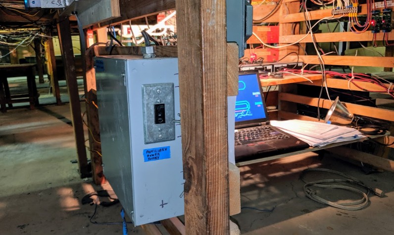
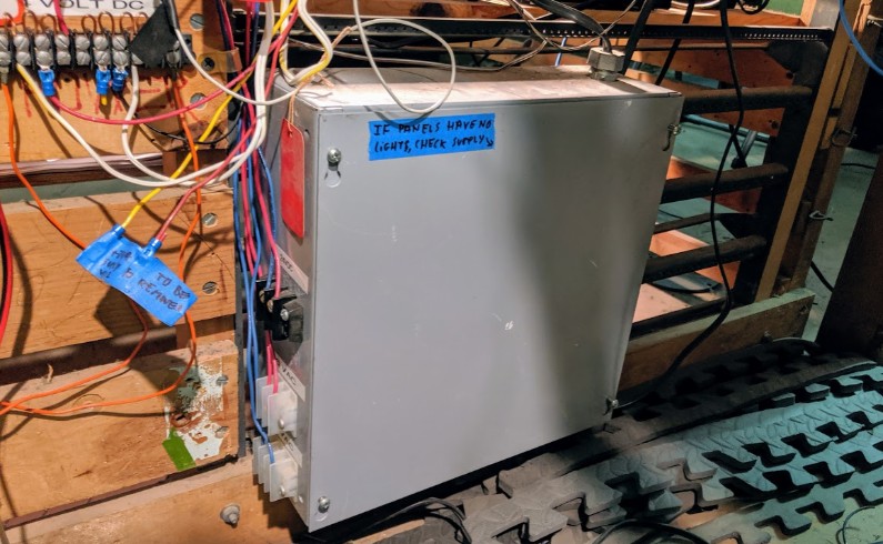
Category RandallThe “Auxiliary Power Supply” is a gray box that used to be located on the other side of the wall behind the automation computer. It has now been moved next to the fascia, just on the other side of the wall where the DCC Power Switch is located. This will make it easier to reset when it trips, which it sometimes does.
It has 3 outputs which provide:
- 24 V DC for the DC / DCC relays.
- 12 V AC for an accessory bus going under the layout, powering various little things (example: tortoise from the branchline, ac-dc converter for the Sonora signal bridge, etc.)
- 6 V AC for … definitely some lights.
The next step is to put a green LED on the front of the power supply. This will make it even more obvious when it has tripped. Also replace the blue painter tape by a proper label. I added the LED but instead went for a contraption like this:
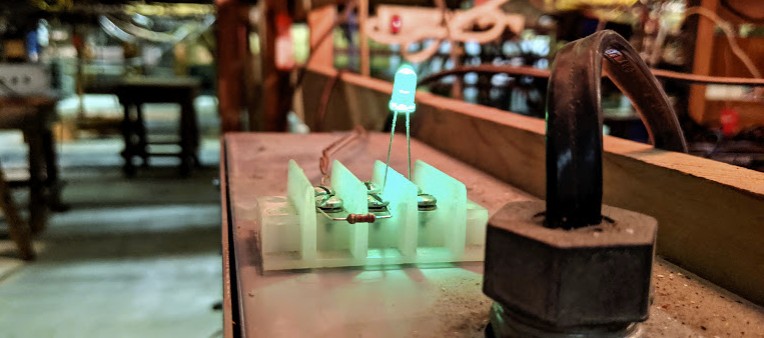
That was a quick test. The idea was instead of putting the LED in front of the box, if I put it at the top, I can also see it when I’m working at the computer without having to lean over. Also I didn’t have any tool to drill the front. I must admit the result is a bit, how should I say, gimmicky. So I’ll probably bring a drill and re-wire it as a LED mounted on the front of the power supply. As for the LED itself, it’s powered off the 6 V AC output with a 2 kΩ 22 kΩ resistor.
Below is a picture of the old location of the power supply. That’s just on the other side of the computer. Problem is that it required crawling under the layout to reset it, which is never a fun experience. Instead now I’ve added a terminal block and pull wires to the new location of the power supply.
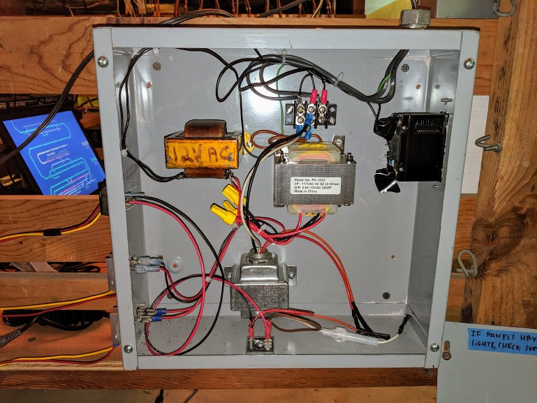
And here’s the inside of the power supply; I’m not sure who did this (George W., very likely?) and I see no need to change anything. It gets the job done.