The Randall Museum in San Francisco hosts a large HO-scale model model railroad. Created by the Golden Gate Model Railroad Club starting in 1961, the layout was donated to the Museum in 2015. Since then I have started automatizing trains running on the layout. I am also the model railroad maintainer. This blog describes various updates on the Randall project and I maintain a separate blog for all my electronics not directly related to Randall.
2019-06-18 - Turnout T06 “Repair”
Category RandallRecently turnout T06 had been out of commission. When throwing it, it would short the mainline. On the layout track plan, this turnout is part of a mainline cross-over in front of the Stockton Yard, which is fairly frequently used by the Saturday Operators -- they can build their train on mainline track #2 and then use that turnout to get it out on mainline track #1, for example.
Usually when I repair something, I made a protocol of documenting what was wrong and how it was fixed. My goal when doing so is to build documentation over time, as well as document changes to the layout. We really lack up-to-date documentation on the technical aspects of the layout besides the few schematics I got from Mr. Perry.

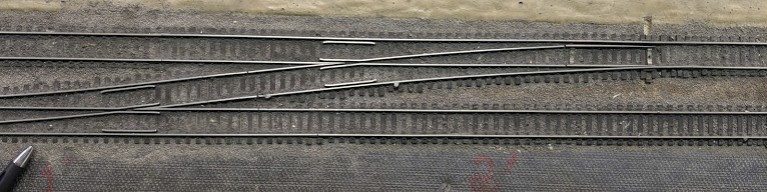
The picture above shows T06 -- which is the cross-over where the SD70 is located. Here’s I’m probing the track to see how the frogs are powered.
The large paper is the schematics I got from Mr. Perry, of which one covers the electrical power routing for the upper part of the cross-over (the track with the blue tape). It is an interesting design which, unfortunately, is a bit of a remnant of a long-gone DC era. Depending on the position of turnouts T05 or T06, the upper track between both cross-overs on mainline #2 is powered by different blocks. This turns out to be a lot of complicated electrical “relay logic” for nothing since all these tracks are ultimately powered by the same booster.
What the schematics I got do not indicate is how the frogs are powered. They are typically switched between both rail polarities based on the Tortoise accessory contacts, and these contacts are also used for other purposes.
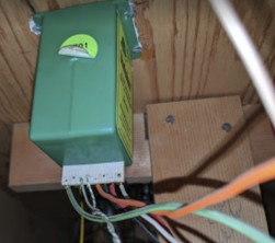
The pen above marks where the soldered connections are for the left-side frog.
This is below the layout, matching the same left-right direction as the track seen from above:
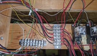

On each Tortoise there are two sets of auxiliary contacts:
- On both Tortoises, a first set of contacts connects to the horizontal terminal block, which in turn powers the frogs.
- On the B01 (left) side, the second set of contacts connects to the signal bridge located ahead of the turnout.
- On the B10 (right) side, the second set of contacts connects to the relay that powers the upper part of the crossover track, via the vertical terminal block.
Here are my notes on the whole thing. I’ll have to redraw proper schematics out of it though:
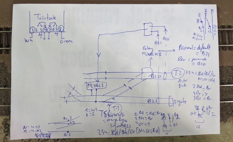
As for actually repairing the turnout… I did nothing specific. It kinda started working again. One screw was loose in the frog terminal block, which I retighten. It’s not enough in my book to consider it a “repair”. Instead I’m thinking there’s probably a bad solder or an almost-broken wire somewhere in all this wiring.
On one hand, I think this all screams to be simplified. Ideally all DCC tracks should be powered by a specific clear DCC bus coming from a clear specific booster. Instead we have a complicated DC power routing, and under the layout we have a confusing heteroclyte mess of power and signal cables bundled together without any kind of identification.
Am I going to do something about it? Nope. Not any time soon. For the simple reason that it works, and I focus my efforts on the automation or fixing parts that are clearly broken. Some folks spent a lot of time on this, they had their reasons, and they did good work, which I am going to respect. I will only address this if and only if it becomes a problem.